
This guide provides clear cost ranges in USD and practical pricing details for U. Typical cost range for a single relay is $2–$150 depending on type and rating. Buyers typically pay a range for relays, and cost is driven by relay type, coil voltage, contact rating, and packaging. This guide presents practical price estimates in USD, with low–average–high ranges and real-world factors that affect total cost. Assumptions: region, specs, labor hours. Relays. The SEL-351 Protection System has built-in Ethernet and IEEE C37. 118 synchrophasors, and is ideal for directional overcurrent applications. Optional Mirrored Bits communications and power quality monitoring add flexibility to solutions. The SEL-351 is the protection standard for utility and. Buyers typically pay a modest amount for small signal relays and higher sums for industrial or specialty units. The main cost drivers are the relay category (signal, automotive, or industrial), quantity, and installation requirements. Although failure of a protective relay system may have severe local or regional impacts, most protective relay systems are not required to operate to prove they are in working order. Ensuring that. What are Protection Relays and How Do They Work? Protection relays are specialized devices designed to detect abnormal conditions in electrical systems and initiate appropriate actions to protect equipment and personnel. These intelligent sentinels continuously monitor electrical parameters and.
[PDF]

87N high-impedance protection requires special class × current transformer cores with equal transformation ratios. The 7SJ60 relay can alternatively be connected in series with the 7UT613 relay to save this CT core. Earth faults on the secondary side are detected by current relay 51N. However, it has to be time-graded against downstream feeder protection relays. Primary circuit-breaker and relay may be replaced by fuses. Go back to contents ↑. Relay 7UT612provides numerical ratio and vector group adaptation. Matching transformers as used with traditional relays are therefore no longer applicable. Line CTs are to be connected to separate stabilizing inputs of the differential relay 87T in order to ensure stability in the event of line through-fault currents. Relay 7UT613provides numerical ratio and vector group adaptation. Go back to contents ↑. The directional functions 67 and 67N do not apply for cases where the transformers are equipped with the transformer differential relays 87T. Go back to contents ↑.
[PDF]
In electric power systems and industrial automation, ANSI Device Numbers can be used to identify equipment and devices in a system such as relays, circuit breakers, or instruments. The device numbers are enumerated in ANSI/IEEE Standard C37.2 Standard for Electrical Power System Device Function Numbers, Acronyms, and Contact Designations. Many of these devices protect electrical. List of device numbers and acronyms• 1 - Master Element• 2 - Time-delay Starting or Closing Relay• 3 - Checking or Interlocking Relay, complete Sequence• 4 - Master Protective. A suffix letter or number may be used with the device number; for example, suffix N is used if the device is connected to a Neutral wire (example: 59N in a relay is used for protection against Neutral Displacement); and suffixe.
[PDF]

This handbook covers the code of practice in protection circuitry including standard lead and device numbers, mode of connections at terminal strips, colour codes in multicore cables, dos and donts in execution. Also principles of various protective relays and schemes including special protection. Read this document and the documents listed in the additional resources section about installation, configuration, and operation of this equipment before you install, configure, operate, or maintain this product. Users are required to familiarize themselves with installation and wiring instructions. presentation of protection and control relaying. The report will identify methodology behind these practices, present issues raised by the integration of microprocessor relays and the internal logic and external communication configurations, ying. The objective of this presentation is to convey a basic understanding of protective relays to an audience of engineers already familiar with low voltage protective device coordination. HT panel protection relay. The HT power supply is received from GO switch and distributed to the. The handbook for protection engineers includes guidelines on protective circuitry, protective relay principles, and testing procedures for switchgear and relays. It covers standard codes, wiring practices, and norms for protecting generators, transformers, and lines, and provides detailed.
[PDF]

Generator protection relays are devices that detect abnormal operating conditions and isolate the generator from the system to prevent damage. These relays act as the first line of defense and are installed with strict adherence to IEC Standard for Protection Relays. Protecting generators from different electrical, mechanical, and thermal stresses is known as generator protection. To safeguard machines from overloads and unusual circumstances, preventive measures are required. Faults are inevitable even with effective design, construction, and operation. Below is an overview of the different types of relays used in generator systems, their functions, and their specific applications. Electromagnetic relays use. Generator Protections are broadly classified into three types: Class A, B and C. Class A covers all electrical protections for faults within the generating unit in which generator field breaker, generator breaker and turbine should be tripped. What Are Generator Protection Relays? Generator protection. There are various protection relays and those are used for protection against a wide variety of conditions. The fundamental principles that are covered in this course are equally applicable to. IEEE C37. 2 defines the IEEE “numerical” function designation for all protective relay functions. This presentation primarily uses the designations from the Beckwith M-3425A relay, which in most cases follows IEEE C37.
[PDF]

A new updated course will be released for sale during the spring of 2026. SFS 6002 Electrical safety -course is mandatory in Finland for all persons involved in electrical works: installers, managers, assistants etc. The course is valid for 5 years and shall be renewed to maintain the. Electrical qualification 1 (Electrical Safety Act 1435/2016 Section 66) The holder of electrical qualification 1 may work as an electrical work supervisor and supervisor of operations in all electrical and operational work. These regulations lay down binding requirements, which cover e. A person who builds, repairs or maintains electrical installations, or repairs and maintains electrical appliances must be professionally qualified, and Tukes must be notified before any such operations begin. The operators are called electrical or lift contractors. A company or a natural person. Electrical safety is not just a legal requirement – it's part of everyday workplace safety. Cad Sä Oy has developed the Electricity Passport, a new training model in which SFS 6002 training is carefully tailored to the specific electrical tasks each participant will perform in their project. The. Finnish electrical safety card (Sähkötyöturvallisuuskortti SFS 6002) is intended for people working in the maintenance and servicing of electrical installations, machines and equipment up to 1000 V in Finland.
[PDF]

This article describes the anti-pumping relay, its definition, function, and circuit diagram. In a circuit breaker it is desired that when close and trip operation is performed on the circuit breaker with the closing coil energized, the subsequent closing operation should be prevented. So let's. Anti-Pumping relay is nothing but a NO contact, which means when the circuit breaker in closed condition the relay will be as NO point and if the circuit breaker in open condition the relay will be as NC Condition. The anti-pumping relays is connected in series with the circuit. An anti pumping relay (also called antipumping relay or Y-relay and ANSI 94 Trip or Trip-Free Relay) is a protective device that prevents a circuit breaker from closing repeatedly when a continuous close command is present. In simple terms, it stops your circuit breaker from “pumping” – which means. Anti-pumping relays are used in circuit breakers to prevent the breaker from closing unexpectedly after tripping. If the TNC switch fails (Trip normal close) or there is any problem with the CB (circuit breakers) closing circuit, the continuous CB (circuit breakers) close command can be extended to. Why is the Anti-Pumping Relay Used? A circuit breaker is a very important equipment for a high-voltage power system. It protects the system from high current or voltage during a faulty condition.
[PDF]

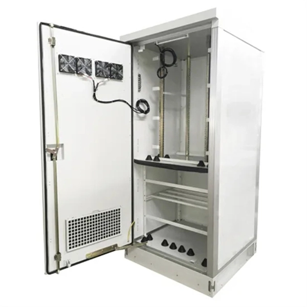
Arduino Safety Relay Box With Wall Socket : A relay is an electrically operated switch. In this project there is no real need to isolate one circuit. Relay rooms are essential in modern commercial or industrial buildings, serving as secure enclosures for electrical relays that manage power distribution and automation systems. Designing a relay room requires balancing technical precision with safety, efficiency, and future scalability. Many relays use an electromagnet to mechanically operate the switch and provide electrical isolation between two circuits. In this article, you will learn how to design an electrical control cabinet for optimal safety and efficiency, following some. This handbook covers the code of practice in protection circuitry including standard lead and device numbers, mode of connections at terminal strips, colour codes in multicore cables, dos and donts in execution. Reliable components ensure system faultlessness and durability. Modern design and user-friendliness. equipment of most. This is Part 1 in a series of tutorials that will show you how to build a Bussmann RTMR fuse/relay block. If you're not familiar with this product, it's a simple waterproof enclosure that allows you to connect accessories on your vehicle through relays and/or fuses. After reading this tutorial, you.
[PDF]
Important transmission lines and generators have cubicles dedicated to protection, with many individual electromechanical devices, or one or two microprocessor relays.OverviewIn, a protective relay is a device designed to trip a when a is detected. The first protective relays were electromagnetic devices, relying on coils operating on moving par. Electromechanical protective relays operate by either, or. Unlike switching type electromechanical with fixed and usually ill-defined operating voltage thresholds.
[PDF]
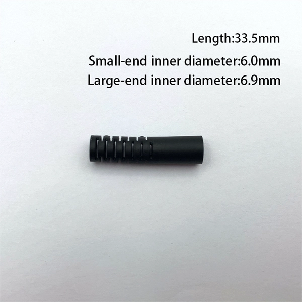
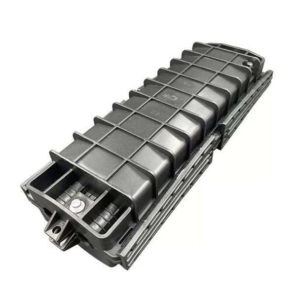
This guide covers everything: what fiber optic pigtails are, how they differ from patch cords, which connector and polish type to specify, how to choose between mechanical and fusion splicing, and the real-world applications where pigtails are the right call. Executive Summary: A fiber optic pigtail is one of the most commonly specified yet least understood components in structured cabling. Get the wrong connector type, the wrong polish, or skip proper fusion splicing technique—and you're looking at elevated signal loss, increased back reflection, and a. In this guide, we'll break down what fiber optic pigtails are, how they work, their types, and how to choose the right one for your application. What Is a Fiber Optic Pigtail? A fiber optic pigtail is a short optical fiber cable that has a connector on one end and an exposed (unterminated) fiber on. When designing or maintaining fiber optic networks, understanding fiber pigtail specifications and fiber pigtail types is crucial for optimal performance and reliability. At JUNPU, we specialize in manufacturing high-quality fiber optic components that meet the most demanding industrial standards. By the end, you will have a comprehensive understanding of why pigtails deserve a place in every fiber deployment toolkit. They are available separately or in kits for ease of installation and ordering. Simplex or multifiber pigtails are available. We also provide a full set of customized services, such as fiber counts.
[PDF]
Legrand continues to be an innovator in cable management solutions and is proud to introduce Cablofil Trough Tray, a cable management system designed to maximize network reliability and minimize lifec.
[PDF]
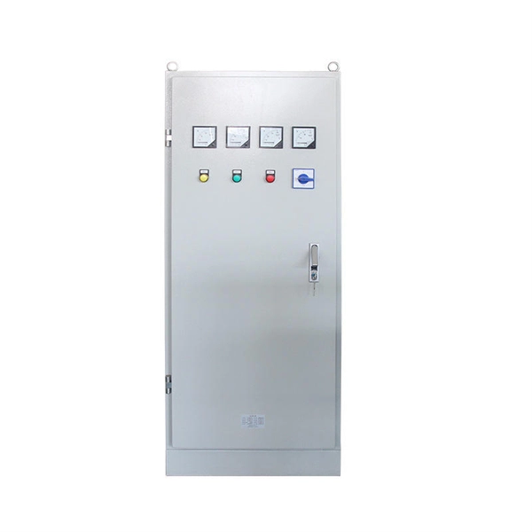
See a sample diagram and download it in different formats. Electrical enclosure sizes are not universal, but most manufacturers follow common size families. This guide explains typical wall-mount and floor-standing dimensions, how to read catalog sizes, and how to choose the right enclosure size for your layout. What Are Electrical Box Dimensions? Electrical box dimensions typically refer to: Correct dimensions ensure:. Solid rubber (construction) distribution box suitable for construction and industry according to EN-61439-4. Available from stock. The only one in the Benelux with a Dekra quality mark. Distribution boxes 32 Amp. Explorez notre Guide Complet du RGIE : Schémas Électriques, Conseils de Conformité, Assistance Gratuite pour la Sécurité et la Mise aux Normes des Installations, et Accès Direct aux Électriciens et Agences Agréées. Discover easy access to the Belgian Electrical Regulations resources, structured. Sheet Electrical: Electricity symbols for floor plans (based on Belgium regulations). Learn more about these objects, how they can be added to your Dia toolbox and how you can draw your diagrams with them. Boxes distribute low currents in an area equipped with 1 to 12 RJ 45 sockets. They centralise connections to ensure flexibility and that the installation is up to date. Area boxes can be installed in technical flooring or in false ceilings.
[PDF]
95 % (Minimum), Pb, Sb, Oxy. 0010 As per BS EN 13601:2018. Corner radii, however can be customized to the customer's requirements. (Full Round edges can be provided in case required by the customer). Cu + Ag - 99. This article explains how the calculator works, the standards it follows (IEC and NEC), and what factors influence. In power engineering, particularly within low-voltage switchgear and packaged substations, copper busbars are the vital conduits for energy transmission. Their precise specification directly impacts a system's safety, reliability, and economic viability. This crucial component demands careful. WILLELE provides high-quality copper comb busbars and DIN rails for reliable circuit connection and modular panel assembly. Our phase distribution and circuit breaker busbars ensure excellent conductivity and precise spacing, while DIN rails are made from galvanized steel or aluminum for easy and. Drawing on international standards, long-term field data, and enclosure-level design experience, we clarify best practices for copper busbar joints —helping designers, engineers, and project managers make safer and more cost-effective decisions. Many engineers assume that increasing the busbar. Select the busbar Material (Copper or Aluminum). Adjust the Safety Factor if needed (default is 25%). Full IEC Verification Enter your base parameters as in the standard method. This. Cu + Ag - 99.
[PDF]
This document provides specifications for various distribution boxes including dimensions, mounting sizes, and number of ways. Electrical control panels and distribution boxes are the backbone of modern electrical systems. From powering homes and industrial facilities to supporting medium-voltage infrastructure, these enclosures ensure safe, efficient, and reliable power distribution. Whether it's a small electrical. Boxes distribute low currents in an area equipped with 1 to 12 RJ 45 sockets. They centralise connections to ensure flexibility and that the installation is up to date. Area boxes can be installed in technical flooring or in false ceilings. Note: Arranged by issue date Note: Arranged by issue date. Have questions or need advice? We can help! Contact Us! White Block Company located in Spokane, WA specializes in Concrete Masonry Units, Architectural Concrete Masonry Units, Chimney Block, Step Stones,. We manufacture and stock Distributions Boxes in various sizes from 3 outlets to 14 outlets:. An outdoor electrical distribution box serves as the critical junction point where incoming power lines are split into multiple branch circuits for outdoor installations, parking lots, building exteriors, and industrial facilities. Unlike standard junction boxes, these distribution systems must.
[PDF]
Optimize your cable management system with this 400×50×3000 mm galvanized wire mesh cable tray —engineered for strength, airflow, and adaptability in a wide range of installations. 8 mm galvanized steel wire, it provides exceptional load-bearing capacity while ensuring long-term. Keep your cables safe and organized with Brilltech Engineers Pvt. We offer top-notch Galvanized Cable Trays in Ghana. These metal trays, coated with a special zinc shield, resist rust and last a long time, even in tough environments. They keep your wires tidy, cool, and protected, from power. Browse our T&B galvanized metallic cable tray systems. More adaptable and easier to maintain than conduit pipe, ideal for evolving wiring needs. Cable tray for arranging cables 100mm by 50mm -300 300mmby 50mm- 500 600mmby50mm-850. Jeetmull Jaichandlall (P) Ltd. We believe in building fruitful business partnerships. Every buyer chooses us first because of our excellent finishing and. Wall mounting brackets and ceiling mounting brackets also available. Metco Limited is one of the leading manufacturers of quality products fabricated from mild steel, stainless steel and aluminium.
[PDF]


