
show interface - To view the configured IP address on the switch. These are the various commands referenced in this document: Updated Grammar and Formatting. Finding the IP address of your network switch is crucial for a variety of tasks, from configuring its settings to troubleshooting network connectivity issues. While it might seem like a technical hurdle, several straightforward methods can help you uncover this essential piece of information. This article provides a comprehensive guide to locating the IP address of a Cisco switch, covering various methods and tools available to network administrators and. Knowing the IP address of your switch is essential for network troubleshooting, configuration, and management. However, finding the IP address of a switch can sometimes be challenging, especially if you don't have access to its documentation or network infrastructure details. In this article, we. This guide will go over how to find the IP address of the M4300 & M4250 and how to access the web interface of the switch. Check the DHCP server to find the new lease from the switch. VLAN 1 default IP address. Two of them are Cisco ones the third one is a D-Link. My predecessor was managing them, unfortunately, when I inherited them I got zero information about it and. Configure the IP address on the switch. Do the next steps to set the system parameters on Catalyst switches that run Cisco IOS software. For details on how to connect to the Console ports of the.
[PDF]

Insert the end of your fiber optic network line into the fiber optic connector on the converter box. Plug an Ethernet cable into the Ethernet port on the converter box and plug the other end into one of the Ethernet ports on the back of your Ethernet switch. As we speak I just have optic fibre (Community Fibre) connected to my Huawei modem / Linksys Velop which will be connected to a new POE switch (need to identify the best model to be compatible with my optic fibre extension project). The objective is to run 1 or 2 additional optic fibre from the. Connecting a fiber optic switch involves several steps, ensuring compatibility between the switch's ports and the fiber optic cable. Fiber optic switches utilize. Fiber optic cabling is increasingly used to connect network switches and other datacom equipment, especially in long-distance and mission-critical applications. Fiber provides: Increased internet signal bandwidth. Advantages Determine the length of the fiber run and choose either multi mode for runs under 1000 feet or single mode for runs over 1000 feet.
[PDF]
What is a core switch, and how does it function? A core switch is a high-capacity network switch that functions as a network's backbone or core layer. It's responsible for accurately routing communication among layers and departments of different sections. Engineered to aggregate massive volumes of data from distribution switches, it provides ultra-low latency and maximum throughput to ensure uninterrupted routing and packet. The core switch is the most important piece of hardware in this infrastructure, acting as the high-speed, central nervous system that ensures all parts of the network can communicate. The core switch functions as the central point of the entire network, forming the high-speed backbone for the. A core switch in networking serves as the high-capacity backbone, italic centralizing data flow and ensuring efficient communication between different network segments. Simply put, it's the kingpin that keeps your network humming. You may also want to know: Can a Nintendo Switch Play DS Games? ·. A core switch is the backbone of a large-scale network, designed to handle massive volumes of traffic with ultra-low latency and maximum reliability. As the central data traffic hub core switch, it guarantees a proper inter-device communication core switch. It's a high-performance switch that provides high-speed connectivity between different network segments, which may include access switches, distribution switches, and routers. The core switch.
[PDF]
The SFP port is a built-in optical port of a Gigabit Ethernet switch, so it cannot be directly connected with a twisted pair or a jumper. It needs to be connected to an optical module first, and then it can be transmitted with an optical fiber patch cord. This chapter describes how to configure Gigabit Ethernet switching on the Catalyst enterprise LAN switches. Note For complete syntax and. Si ce produit est vendu au Canada, vous pouvez accéder à ce document en français canadien à https://www. com/support/download/. The RJ45 port is for copper cable. al installation guidelines and recommended procedures. To deploy this switch effectively and ensure trouble-free operation it is recommended to first read the relevant sections in this guide so rk administ tors and support personnel that install, e is based h relevant specif tions and. This command is configured in layer-2 interface configuration mode. The optical interface speed is fixed. The optical/electric port cannot support the gigabit and full-duplex at the same time. The ordinary TX port does not. The guidelines for configuring speed on QFX5100-48T switch are as follows: If the speed on the switch is set to 10-Gbps or auto, the switch advertises all the speeds. If you have configured the speed to 100 Mbps.
[PDF]
Access your Nintendo Switch console using your current account. Go to the main menu and select "Configuration" to access the console settings. Within the settings, navigate until you find the option "Users". Learn how to update your Nintendo Account information, including email address, country, and more. Please read our information on changing Nintendo Account passwords. 2-step verification adds an. How to change account settings on your Nintendo Switch La Nintendo Switch is a versatile and popular video game console that offers a wide range of customizable features. Whether you want to modify your existing account. Each person can sign in with their own Nintendo Account, which lets them customize their profile settings, access online game modes, redeem their My Nintendo rewards, and purchase content from the eShop with their own payment options. Access the home menu of your Nintendo Switch and select the “Settings” option. I started playing core when it first came out and i dont know how to change my username from old to a new one. You can't change it on your own. I'd recommend submitting a support request. AFAIK there is no limit in the number of accounts a physical player may own. Manticore does not punish a.
[PDF]
Each version of Nintendo Switch has its own dedicated SD card slot. Adding a microSD card to your Switch is pretty easy. You will find the Nintendo Switch memory card slot at the back side of the Switch near the bottom of the console. Struggling to find the microSD card slot on your Nintendo Switch? This quick guide will show you exactly where to locate it and how to properly insert or remove your memory card to expand your console's storage. 512 microSDXC Memory Card, UHS-I, C10, U3, V30, A2, Full-HD Video, Up to 100 MB/s, Expanded Storage for Nintendo-Switch, Gaming. This guide will tell you everything you need to know about the Nintendo Switch 2's internal storage and memory, how many games you can store, and how you can increase your storage space. On this page: Nintendo Switch 2: Internal Storage - How Many Games Can You Store? 1. This will not change whether downloadable software or software from a game card is being played. Game save data cannot be saved or copied to a microSD Express card. Nintendo Switch Online members can use Save Data Cloud. These cards are small, but they can significantly expand the console's storage capacity, allowing you to download and store more games and content. The memory card slot is cleverly hidden to maintain the sleek design of the console, which can make it a bit tricky to find if you are not familiar. Check each product page for other buying options.
[PDF]

Run the loopback-detect untagged mac-address ffff-ffff-ffff command in the system view to broadcast BPDUs for loopback detection and prevent them from being terminated by unexpected devices. Huawei's comprehensive portfolio of products and solutions enables you to realize smooth digital transformation and rapid growth of virtualization, Big Data, and cloud services. Huawei switches already help customers achieve success in industries such as finance, Internet, retail, education. Plan the network configurations, configure loop prevention protocols, and enable loopback detection to prevent loops. They provide ultra-high-density 10GE/40GE/100GE/200GE/400GE full-rate access ports, meeting customers' requirements for quickly building campus networks with a simplified. CloudEngine S12700H series switches are Huawei's next-generation modular core/aggregation switches designed for high-end campus networks in the all-wireless era of Wi-Fi 6/7. CloudEngine S12700H series switches come in two models, which offer four and eight LPU slots, respectively. The S9700 uses an advanced multilayer switching architecture to support sustained bandwidth upgrading and to provide 40GE. This document provides campus networks typical configuration examples and feature typical configuration examples. "Campus Networks Typical Configuration Examples" provides typical campus network networking modes and a variety of deployment examples.
[PDF]

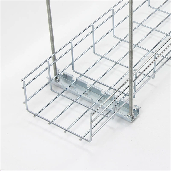
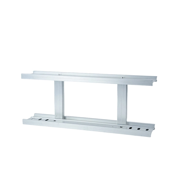
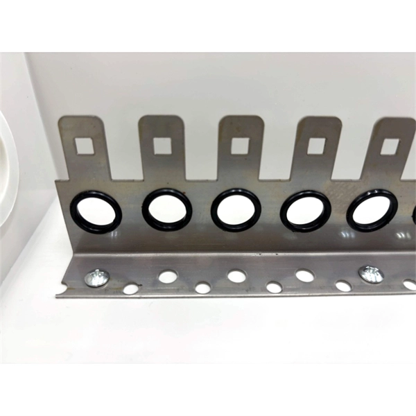
Cable Trays* — Max two 24 in. (610 mm) wide by max 6 in. (151 mm) deep open-ladder cable tray with channel-shaped side rails formed of 0. 54 mm) thick aluminum or min 0. In practice, cable tray dimensions are a system of interrelated measurements —width, depth, length, and material thickness—that directly affect cable fill compliance, heat dissipation, structural loading, and long-term expandability. From an engineering standpoint, cable tray dimensions are not. Perforated Cable Tray System expertly constructed from high-grade stainless steel, offering exceptional durability and resistance to corrosion. With side height 100mm. A properly designed and installed cable tray system will provide. Studs — Wall framing to consist of wood studs or channel shaped steel studs. Wood studs to consist of nom 2 by 4 in. Additional studs shall be used to completely frame. Best Size: Here, deep trays (75mm to 150mm) are used since power cables are typically thick and heavy. Data cables, such as your Wi-Fi or computer ones, are extremely sensitive. They do not get hot; however, they do not like to hang or sag. In case a data cable folds in an excessive manner, the. ect the minimum bend ra-dius for cables as they exit the bottom of the cable tray. A rung spacing of 6 to 9 inches (150 to 230 mm) is preferable when the cable tray cont d for instrumentation and control applications that require additional protec eferred to support and protect numerous small.
[PDF]
It can be seen from the above that the aggregation switch has functions such as source address, destination address filtering, real-time policy, security, network isolation, and segmentation. Compared with access switches, aggregation switches have better performance and higher. What is an Aggregation Switch and How Does it Work? An aggregation switch consolidates data traffic from multiple network access switches into a single high-bandwidth link directed toward a core network or data center. The primary function of an aggregation switch is to aggregate and forward data. A fiber optic aggregation switch is a high-capacity network device designed to integrate and manage multiple fiber optic connections from access layer switches into fewer and faster uplink connections to the core network. It is essential for larger networks requiring efficient data flow. You may also. All-optical Ethernet switches are a type of switch that provides optical uplink and downlink ports, making them an ideal choice for building an all-optical campus network. They can function as core, aggregation, and access devices on campus networks and connect to upstream and downstream devices. As the physical entity of the aggregation layer, the aggregation switch's primary function is to aggregate the data of the access layer switch and forward it to the core switch to reduce the burden on the core layer. Cisco's aggregation switch What is the Role of the Aggregation Switch in the.
[PDF]
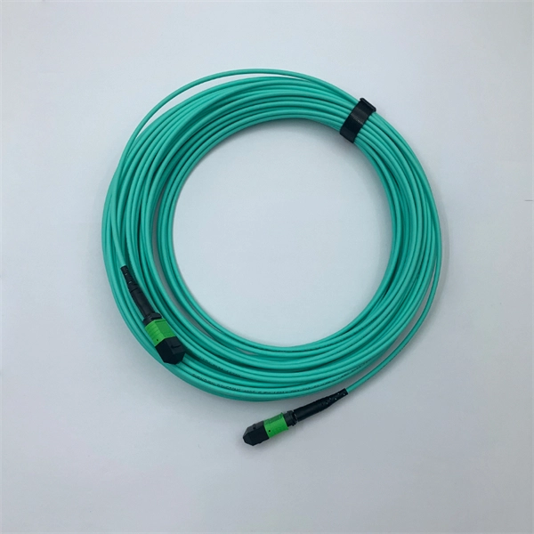
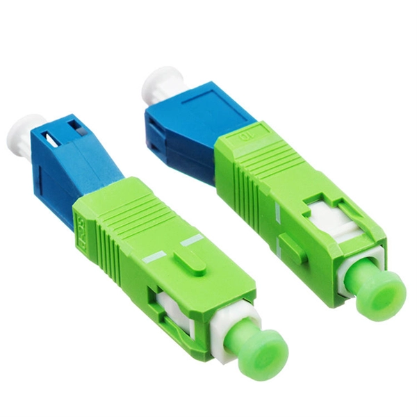
Connect the fiber optic cable: Attach the fiber optic cable's connector to the transceiver module on the switch. Make sure the connector type (e., SC, LC) matches the transceiver module. In addition, fiber cables can transmit data over several kilometers without signal degradation, making them ideal for connecting switches in large campus networks and between different buildings. As they do not emit electromagnetic signals, they're difficult to tap and secure against eavesdropping. Fiber optic cabling is increasingly used to connect network switches and other datacom equipment, especially in long-distance and mission-critical applications. Fiber provides: Increased internet signal bandwidth. Most modern fiber-enabled network switches require an SFP transceiver module. As we speak I just have optic fibre (Community Fibre) connected to my Huawei modem / Linksys Velop which will be connected to a new POE switch (need to identify the best model to be compatible with my optic fibre extension project). The objective is to run 1 or 2 additional optic fibre from the. Choose an SFP module based on the fiber optic cabling that will be connected to the network switches. SFP transceiver modules almost always require two fiber optic cable strands. Even the most advanced optical transceivers can only perform at their peak when paired with properly installed, clean, and precisely managed fiber.
[PDF]
Fiber optic switches are devices used to control the flow of light in fiber optic networks. They are used in a wide range of applications, including telecommunications, data centers, industrial automation, and military and aerospace. This piece analyzes how these switches can make a difference today. Fiber optic switches offer numerous advantages over traditional. A fiber optic switch is an electronic device that allows multiple fiber optic cables to be connected and selectively route data between them. The switch receives data packets from one input fiber optic cable and forwards them to the appropriate output cable based on their destination addresses. It operates on the same principle as an electrical switch, but instead of using electrical signals, it uses light signals to switch data packets from one fiber optic cable to another. Fiber. A fiber optical switch, also known as a fiber channel switch or a SAN (Storage Area Network) switch, is a high-speed network transmission relay device. This technology offers significant.
[PDF]
The layer 2 switches prevent over-crowding of data packets in transmission links and access devices. · Layer Positioning: The data link layer (Layer 2) of the OSI model, realizing local forwarding of data frames based on MAC addresses. · Core Task: Establishing direct interconnections between devices within a local area network to ensure efficient communication within the same network segment. ·. The core layer is the backbone of the network. It provides a high-speed connection between different distribution layer devices. The distribution layer connects the access layer to the core layer. When designing a campus LAN, you may. In enterprise networking, the hierarchical three-tier model is divided into three distinct roles: access switches (which connect end-user devices to the network via Layer 2), distribution switches (which route inter-VLAN traffic and enforce security policies at Layer 3), and core switches (which. The core switch is the most important piece of hardware in this infrastructure, acting as the high-speed, central nervous system that ensures all parts of the network can communicate. The core switch functions as the central point of the entire network, forming the high-speed backbone for the. Distribution Layer: The distribution layer is an intermediate layer. Simply put, it's the kingpin that keeps your network humming. You may also want to know: Can a Nintendo Switch Play DS Games? ·.
[PDF]

RG-CS85-24GT8XS-D 24-Port 1GE RJ45 Layer 3 Enterprise-Class Core or Aggregation Switch, 8-Port 10GE Uplink Highlight Features Rich port types, 24 x 10/100/1000BASE-T ports, and 8 x 1GE/10GE SFP+ ports for uplink Hardware redundancy, guaranteed service continuity and network. RG-CS85-24GT8XS-D 24-Port 1GE RJ45 Layer 3 Enterprise-Class Core or Aggregation Switch, 8-Port 10GE Uplink Highlight Features Rich port types, 24 x 10/100/1000BASE-T ports, and 8 x 1GE/10GE SFP+ ports for uplink Hardware redundancy, guaranteed service continuity and network. Aggregation switch for small and medium-sized campus networks, with eight 10G uplink optical ports for high-speed data transmission; 24 x 10/100/1000BASE-T ports, providing high-speed network experience for short-distance services. Core switch for small and medium-sized enterprise networks, with. Hello, my name is Bob, and I am a Senior Engineer with the Technical Services team at network-switch. I am also a certified Cisco CCIE professional and HCIE certifed engineer, which reflects my expertise in networking and my dedication to delivering high-quality technical solutions. I. 24-Port 1GE RJ45 Layer 3 Enterprise-Class Core or Aggregation Switch, 8-Port 10GE Uplink Highlight Features VSU virtualization, flexible networking and high reliability. The VSU connects to peripherals through an aggregate link, realizing service switching in milliseconds upon a failure.
[PDF]
Check CORE SWITCH price from the latest Cisco price list 2022. Public Procurement Regulatory Authority (PPRA) is an autonomous regulatory body established under the Public Procurement Regulatory Authority Ordinance, 2002. Operating under the Cabinet Division, Government of Pakistan, PPRA is entrusted with the responsibility to ensure transparency. al Investment Project. For this contract, the borrower shall process the payments using the open. In today's digital world, reliable and robust network connectivity is crucial for businesses of all sizes. Networking switches play a vital role in facilitating this connectivity by enabling communication between devices within a network. This article will delve into the intricacies of networkin. Looking for the Best Networking Solutions? Visit IT Network Services. Providing network equipment and solutions. Buy A4tech, Cisco, HP Servers, Dell Servers, and Fortinet brand products in Pakistan. Subscribe our newsletter to get our latest update & news. Find the best Core Switch price in. For the sample orders, if it met with the Free Shipping policy, then shipping and delivery cost would be covered by NADDOD. tariff for customs clearance if any) should be borne by buyer. The sample orders. Choose the option that suits you best: Request a Quote: If you would like a personalized quote based on your specific server needs, simply fill out the form below.
[PDF]
Includes dual power supplies, hot-swappable modules, link aggregation (LAG), and support for HSRP/VRRP. Modular chassis or stackable designs make it easy to scale as your network grows. 1X support, SNMP, CLI/Web GUI, and network access control. There are different types of enterprise switches that perform various roles in these layer-based or hierarchical ethernet networks. This white paper introduces the following three types of network switches and further discusses the selection criteria for each switch. What is a network switch? So, what is a network switch? A network switch is a vital component of a computer network that. What is Spanning Tree Protocol (STP) and why is it important in core switch networks? Can I use a cloud-managed core switch? How does Quality of Service (QoS) impact core switch performance? What Is a Core Switch in Networking? Understanding the Backbone of Your Network A core switch in networking. Providing The Most Competitive Networking Products For Global Customers! In the realm of system networking, three key types of switches are frequently mentioned: access switches, aggregation switches, and core switches. The part of the network that directly connects to user devices is referred to. What Is a Core Switch? The Definitive Guide to Network Architecture A core switch is a high-capacity, high-performance Layer 3 switch positioned at the physical backbone of an enterprise network. This post mainly explores the confusing problem: core.
[PDF]