
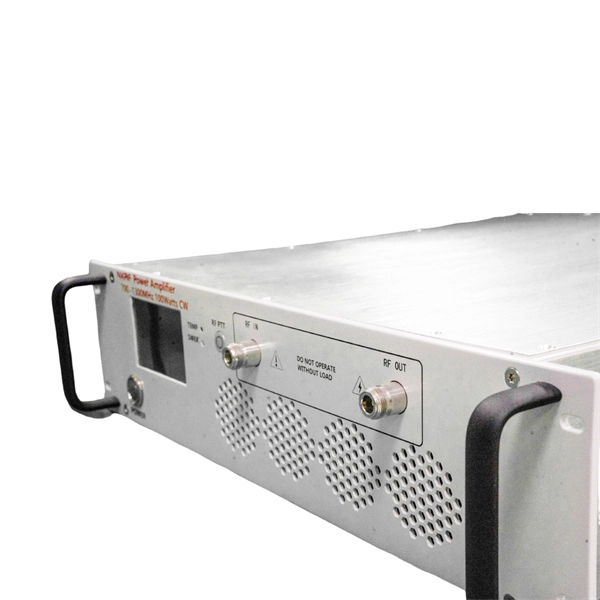
In this video, we'll walk you through the process of resurrecting y. The test sets display a laser warning icon when the laser source is active to alert the user about a potentially dangerous situation. It is recommended to: Deactivate the laser before connecting or disconnecting optical cables or patchcords. more Is your optical power meter showing no signs of life? Don't worry; we've got you covered! In. Introduction The RP460 Optical Power Meter is an ultra low cost, and compact power meter used for verifying both absolute and relative power across any given fiber. This document will serve as an overview of the major features and functions of the device and will offer tips for trouble shooting. Fiber Optical Powermeter User Manual | FS Title Author Subject Keywords Created Date. The OPM1315 is a newly developed portable optical power meter. It is equipped with a 1. 0 mm large area detector so that stability and reliability can be enhanced effectively. This unit is designed to fit the hand comfortably, and can be used for installation, debugging, and maintenance of any fiber. ments to the instrument's performance and functionality. The figures given in this manual ion of this manual to ensure the accuracy of its contents. However, should you have any questions or fi gistered users with a variety of information and services. Please allow us to serve you best by.
[PDF]
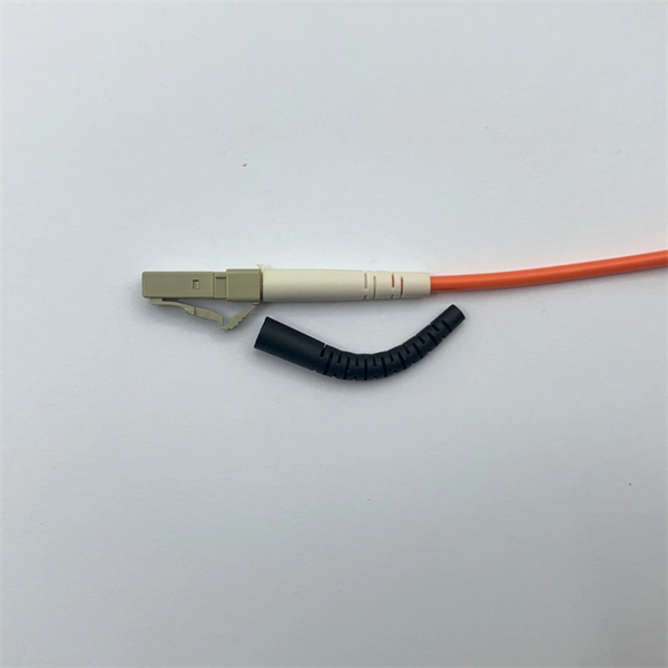
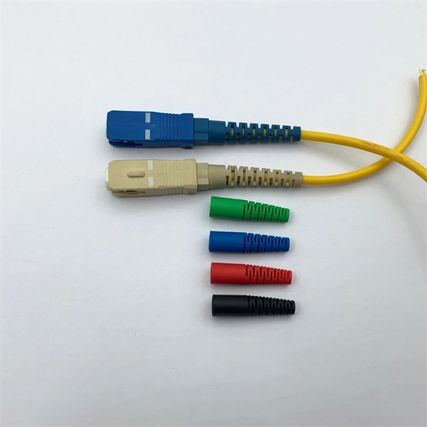
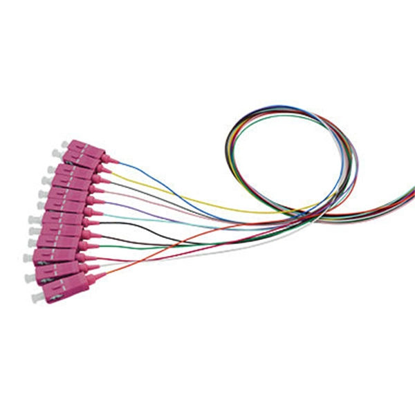
Trending price is based on prices over last 90 days. Find many great new & used options and get the best deals for 3M 6366 Hot Melt Fiber Termination Kit 120v Tested at the best online prices at eBay! Free shipping for many products!. Trending price is based on prices over last 90 days. The result is a quick mount. The 8602-S Hot Melt LC is a singlemode. Check each product page for other buying options. Need help?. FS fiber optic pigtails offer a fast way to make fiber optic communication devices in the field by fiber splicing, fully manufactured and tested by industrial standards. 3M Model 6312 Hot Melt Fiber Optic Connector Termination Kit WITH CASE & EXTRAS! item 3 3M Model 6312 Hot Melt Fiber Optic Connector Termination Kit WITH CASE & EXTRAS! Wiha Tools 91872 Master Electrician's Insulated Tool Kit 59 Pc. Find many. TXM's Quick Assembly Hot Melt connectors provide a quick and easy termination of fibers in the field. Our field connectors are universal and applicable for 0. 9mm Tight Buffer Fiber, 2. These field connectors allow the installer to terminate fiber in minutes out in the. Log in or register to view your price, purchase history, and more! The Hot Melt Termination Kit 6366 contains all materials needed to install SC, ST and FC Hot Melt Connectors, both multimode and single-mode. Kit comes with a 120V oven. 3M Hot Melt Termination Kits 6366 (120V oven) and 6362 (230V.
[PDF]

show interface - To view the configured IP address on the switch. These are the various commands referenced in this document: Updated Grammar and Formatting. Finding the IP address of your network switch is crucial for a variety of tasks, from configuring its settings to troubleshooting network connectivity issues. While it might seem like a technical hurdle, several straightforward methods can help you uncover this essential piece of information. This article provides a comprehensive guide to locating the IP address of a Cisco switch, covering various methods and tools available to network administrators and. Knowing the IP address of your switch is essential for network troubleshooting, configuration, and management. However, finding the IP address of a switch can sometimes be challenging, especially if you don't have access to its documentation or network infrastructure details. In this article, we. This guide will go over how to find the IP address of the M4300 & M4250 and how to access the web interface of the switch. Check the DHCP server to find the new lease from the switch. VLAN 1 default IP address. Two of them are Cisco ones the third one is a D-Link. My predecessor was managing them, unfortunately, when I inherited them I got zero information about it and. Configure the IP address on the switch. Do the next steps to set the system parameters on Catalyst switches that run Cisco IOS software. For details on how to connect to the Console ports of the.
[PDF]

The typical thickness of a glass core can range anywhere from 8-10 um (microns) for single-mode and 62. 5-50 um for multimode; these core sizes are the most prevalent ones utilized in the telecommunications industry. The core of a conventional optical fiber is the part of the fiber that guides the light. It is a cylinder of glass or plastic that runs along the fiber's length. The core is surrounded by a medium with a lower index of refraction, typically a cladding of a different glass, or plastic. The light is transported along the optical fiber via its smallest and most crucial component, which is called the core. However, they are composed of many components, each constructed from advanced materials to guarantee the quick and reliable transmission of data. So, let's break it down! The core is the primary part of a Fiber optic cable. It's responsible for. The 8 Core Multimode Outdoor Fiber Optic Cable is designed for high-performance data transmission in various outdoor environments, making it an ideal choice for telecommunications, networking, and data center applications. We supply single mode GYTS fiber optical cable and multimode GYTS fiber optic cable, fiber strand from 2 cores to 432 cores. A related GYTA type cable is available. This advanced cabling solution allows fast, secure data transfer and telecom over long distances. Understanding the components within a fiber optic cable enables.
[PDF]

In today's video, we'll be unboxing the 9-Port Power Supply Box and demonstrating how to connect the cables to provide power to CCTV cameras. A CCTV power supply box sends power to all your cameras from one place. It helps keep things neat and makes your system easier to manage. In this guide, you'll learn how to install it step by step, choose the right type, avoid common problems, and keep your system running safely. Power supply boxes for CCTV are typically used in multi-camera installations instead of using single power adapters for each camera. The process is almost exactly the same if you. Installers of surveillance systems may simply control the power to various CCTV cameras using a CCTV power supply box, also known as a power distribution box (usually at the location of the DVR). This enables a cleaner camera installation. Surge protection can be accomplished in two ways. The power supply box is specifically used to transfer power requirements for all cameras plugged in on the system, to work. Security cameras use RG59U coax siamese wire or CAT5e networking cable to transmit video. Whether you are installing a power box for a new or existing camera system, it is important to understand how to connect cameras to a CCTV Power Supply Box. DC current is polarized meaning it has two leads, a.
[PDF]
The typical cost of 1U space in a 45U server cabinet is $55. Therefore: Average cable management cost is . Basic cable management systems (cable trays, ties): $200 to $1,000 per rack. Power and Cooling Infrastructure Power Distribution Units (PDUs): $200 to $1,500 per unit, depending on capacity. 73/U The. Durable & Easy to Install: Made from sturdy plastic for long-term use in IT environments. Installs easily on standard rack rails using the included M6 screws-no special tools required Each item has a unique code that we verify before shipping. com Return Policy: Amazon. com. Sysracks offers a wide array of data closet cable management products for different devices: Horizontal managers: Our 1U wire managers are designed to suit any 19” cabinet. This allows structured routing of twisted-pair wires and patch cords and ensures the correct cord radius to prevent twisting. Shop top-quality rack cable managers for efficient data center wiring. Get a horizontal/vertical cable manager to safely organize and protect your cables. Our 1U and 2U cable managers reduce slack, improve airflow, and create clean, serviceable rack layouts designed for scalability.
[PDF]
In this tutorial, we will show you how to fusion splice two fiber optic strands together in an easy 12 step process. The answer lies in splicing, both fusion and mechanical. Whether you're a professional technician or a DIY enthusiast, understanding the process of fusion splicing fiber optic cables is essential for maintaining high-speed communication networks. - Fiber Instrument Sales What is Fusion Splicing? How fiber optic splicers work, types, what they are used for. Steps to use this equipment and including how to test your fiber splice. The guide covers everything from basic principles of fusion splicing to detailed procedures; it is intended to provide both newbies and professionals with the necessary knowledge and skills. The operation and skills of fiber optic fusion splicing technology can be mainly divided into five steps: fiber stripping, fiber cutting, fiber melting, fiber sleeve, and fiber winding. And tools used for fiber fusion: fusion splicer; fiber cleaver; cable stripper; fiber optic stripper; alcohol;.
[PDF]
In this guide, I'm excited to share with you 15 creative and surprisingly simple ways to transform your ugly electrical box from an eyesore into a part of your home you might actually want to show off. There are actually a whole host of creative and, more importantly, stylish ways to conceal your breaker box or electrical panel without blocking access or impeding functionality. But before you get started, make sure you double-check with an electrician and your local codes. Some electrical codes. Either way, here are unique electrical panel cover ideas to give you some inspiration. Don't let an ugly gray metal electrical panel ruin your decor! Check out these creative solutions for covering one in any room (removable, of course). Our editors and experts handpick every product we feature. We may earn a commission from your purchases. Which is exactly where I was struggling, we have an electrical panel directly in our dining room (small space problems). These fellow bloggers turned their electric panel doors from eyesores into focal points and pieces of art.
[PDF]

While optical power meters are the primary power measurement instrument, optical loss test sets (OLTSs) and optical time domain reflectometers (OTDRs) also measure power in testing loss. TIA standard test FOTP-95 covers the measurement of optical power. This measurement is the basis for loss measurements as well as the power from a source or presented at a receiver. Typically both transmitters and receivers have receptacles for fiber optic connectors, so measuring the. You need a power meter to measure power in a fiber optic system; most power meters come with a screw-on-adapter that matches the connector being tested and a little aid from the network electronics to turn on the transmitter. During the measurement of power, the meter must be set to the proper. Fluke Networks sets the standard in network testing with its advanced range of fiber optic power meters and fault locators, designed to ensure the highest precision in fiber optic meter readings and power evaluations. This is measured in decibels (dB). Splitters, fusion splices, connectors and. To use a power meter for fiber optic testing, always clean connectors first with lint-free wipes or click-to-clean tools. Select the correct wavelength and set your reference. Consistent procedures ensure accuracy.
[PDF]

The first thing you should do is locate the fiber optic cable that comes from the service provider. Once inserted, make sure it is securely. However, setting up a fiber optic connection to your router can seem daunting if you're unfamiliar with the process. Why Use Fiber Optic Internet? Before diving into the setup, let's quickly. Ensure your fiber optic router has an available WAN (Wide Area Network) or Ethernet port for the fiber optic modem. It's thin, flexible, and usually comes with connectors on both ends. Power Cables: Get power cables for both the. The fiber optic cable does not plug directly into a standard home router because the signal type must be translated. The fiber line terminates at the Optical Network Terminal (ONT), which is typically supplied and installed by the internet service provider. This specialized equipment serves as the. The process to connect fiber optic cable to router requires careful attention to detail, but I'll walk you through every critical step with the precision and clarity you deserve. Here's a step-by-step guide to help you through it. Understand the Basics Before diving in, familiarize yourself with the components involved:. Follow along as we take you through the step-by-step process of installing fiber internet! From preparing the site to connecting the final cables, we'll show you what goes into bringing high-speed internet to your doorstep. Whether you're a tech enthusiast or just curious about how it all w.
[PDF]

Excavate the cable at the break point and use a fiber optic cutter to remove the damaged section. Use a high-precision fiber cleaver to prepare the fiber ends for splicing. Step1 : Identify the optical cabinet and network operating center, and find the fiber optic splitter. Step 2: Identify the splitter number. Step 4: Find the optical fiber port and cable sequence that leads to the user. 2) The. Here are the steps to patch a fiber cable. Make sure the connectors are free from dust or dirt and that there is no damage to the cable's. When fiber cables sustain damage, specialized repair techniques help restore connectivity and maintain data integrity. This comprehensive guide outlines professional fiber optic repair protocols that align with industry best practices. Adhering to precise methodologies, we can mend impaired cables. Learn how to splice fiber optic cable step by step in this complete guide! In this video, you'll see the full fiber splicing process — from fiber preparation, cleaving, and fusion splicing to final testing. Whether you're a network technician, IT professional, or telecom operator, you'll find practical steps, tools, and tips to restore. By understanding these key elements and following the outlined steps, you can effectively repair fiber optic cables and maintain the high-performance network necessary for today's demanding communication needs. When it comes to ensuring nice network experiences for users, the condition of a fiber.
[PDF]

Optical modules (also known as fiber optic transceivers) are essential components in modern communication networks, enabling high-speed data transmission by converting electrical signals into optical signals and vice versa. Among various optical module form factors, SFP (Small Form-Factor Pluggable). A fiber optic transceiver (also called an optical transceiver) is a compact module that both transmits and receives data signals through optical fibers. It serves a dual purpose — transmitting electrical signals as light pulses and receiving light pulses to convert them back into electrical form. An optical module usually consists of an optical transmitting device (TOSA, including a laser), an optical receiving device (ROSA, including a photodetector), functional circuits,main control circuit board (PCBA), housing and optical (electrical) interface and other components. How do optical. At the heart of fiber optic technology lies a crucial component: the optical transceiver. Let's explore the key aspects of optical transceivers to help you navigate.
[PDF]

In this tutorial, I will show you how you can connect the Optocoupler to Arduino, read the data as Analog or Digital, and if necessary convert the analog values to digital, and how to reduce noise from the sensor. The Infrared Slotted Optical Optocoupler Module is a device that uses infrared light to transmit signals between two electrically isolated circuits. It consists of an infrared emitter (LED) and a photodetector (phototransistor) housed in a slotted enclosure. When an object passes through the slot. Slotted Optocouplers (Photo Interrupters) are very useful sensors, often included in Arduino projects to detect position of moving objects, measure speed of rotation, or linear motion, frequency of events, and many others. They are easy to use, but it is important to understand how they work, so. This tutorial is a comprehensive, practical guide to the Speed Sensor / Tacho Sensor (Slot-Type Optocoupler) (Leobot Product #245). Moreover, a simple application is programmed that shows how to wire and how to program an Arduino when working with the module. In this tutorial, the module is used as an “digital input board”. If you want to use the. In this project, I will talk about Phototransistor Optical Interrupter Switches (Opto Coupler) Module, how this module works and helps in determining the speed of a rotating object and finally I will show you how to Interface Optical Interrupter Switch Sensor with Arduino and measure the speed of a.
[PDF]

With the large variety of beamsplitters available, the designer needs to take many factors into consideration. This article and its illustrations will go a long way toward making the correct choice less of a risk. All curves show typical performance. A beam splitter (or beamsplitter, power splitter) is an optical device which can split an incident light beam (e. a laser beam) into two (or sometimes more) beams, which may or may not have the same optical power (radiant flux). It is a crucial part of many optical experimental and measurement systems, such as interferometers, also finding widespread application in fibre optic telecommunications. One beam is typically reflected while the other is transmitted. Beamsplitters are often classified according to their construction: cube or plate. In this blog, we will explore the step-by-step process of using a beamsplitter cube effectively, along with some common applications that benefit from this powerful optical tool. Step-by-Step Guide on Using a Beamsplitter Cube Step 1: Understanding the Cube Orientation: A beamsplitter cube is a. A beam splitter is an optical device that splits beams (such as laser beams) into two (or more) beams. Beam splitters typically come in the form of a reflective device that can split beams into exactly 50/50, half of the beam being transmitted through the splitter and half being reflected.
[PDF]
Explore verified suppliers offering low-price fiber optic splice boxes, ideal for wholesale. With options from 24 to 144 cores, start your purchase from 1 unit at an average price around $17. This fiber optic splice box is an outdoor fiber optic splice closure used to protect the twisting and joining (splicing) of fiber optic cables. These splice boxes are not made for in-house, off-the-shelf cabling solutions. Instead, they are for installation by professionals laying new fiber optic. Check each product page for other buying options. Price and other details may vary based on product size and color. Need help?. All products' documentation is published in PDF (Portable Document Format), which requires Adobe Reader (ver. 5 and newer) software for viewing. Though we pay utmost attention, we cannot guarantee, that published materials are free of errors and diversities. These lapses cannot be a basis for any. Longevity: Properly installed plastic splice boxes can reliably perform for 10–15 years or more, depending on climate and usage conditions. Best for: Telecommunications, low-voltage systems, residential wiring, and temporary installations where cost and ease of installation are priorities. These kits ensure minimal signal loss and maximum reliability in telecommunications, data centers, and broadband networks. Proper splicing maintains signal.
[PDF]