To use a power meter for fiber optic testing, always clean connectors first with lint-free wipes or click-to-clean tools. Select the correct wavelength and set your reference. You measure optical power in dBm or insertion loss in dB. Consistent procedures ensure accuracy. Verify light travels from. The most basic fiber optic measurement is optical power from the end of a fiber. This measurement is the basis for loss measurements as well as the power from a source or presented at a receiver. Typically both transmitters and receivers have receptacles for fiber optic connectors, so measuring the. An optical power meter measures the strength of light traveling through a fiber optic cable, giving you a reading in dBm (decibels relative to one milliwatt). This article will guide you through the methods, instruments, and key considerations for measuring fiber. Fiber optic cabling is the high-performance core of today's datacom networks. As network speeds and bandwidth demands increase, fiber performance requirements have become more stringent. Fiber testing is more important than ever. An OPM uses a photodiode to generate an electrical current proportional to optical power.
[PDF]

Optical Fiber Communication (OFC) revolutionizes modern telecommunications, enabling rapid data transfer across long distances with minimal signal loss. This comprehensive review explores OFC's historical evolution, core principles, components, and versatile applications. It traces OFC's. Additionally, optical fiber is lightweight and less susceptible to noise (no electromagnetic induction). Optical fiber consists of a cylindrical core that propagates light and a concentric cladding that surrounds it. The cladding's refractive index is slightly smaller than that of the core, which. Fibre optics and optical communications is the use of thin strands of glass for sending information encoded into light over long distances. Total internal reflection prevents light inserted into one end of the fibre from escaping through the sides. Keywords: Optical fibers, communication systems, data. Figure 1: Illustration of the inverse-square law of light intensity – the light's intensity diminishes with the square of the distance, which free-space optical signals must overcome (leading to very weak reception at long range) Figure 1 illustrates how light intensity decreases as distance.
[PDF]

Fiber Optic Welding How To Joint Fiber Optic Cablesplicing fiber optic cable,fiber optic splice,fiber optic,fiber optics,fiber splice,how to splice,fibre opt. The optical fiber connection adopts the fusion splicing method. The whole process is similar to the welding of metal wires, and it is generally carried out by electric isolation. At the moment, there are two methods of connection: Thermal welding of optical fibers consists in bringing the ends of the conductor to melting using a fiber optic splicer, and more specifically - located inside the electrodes. The welded ends are then pressed and a weld is formed. The most work is waiting for installers, whose tasks can be divided into several stages: In this part, we will deal with the second stage, i. welding, which is considered to be one of the most difficult parts of installers' work in. Open the stripping tube and wipe the grease on the optical fiber with toilet paper and alcohol cotton. On the welding disc, make the optical fiber precoil first and cut the optical fiber into an appropriate length to facilitate the coil fiber work after welding. Add heat shrink tube. Procedure. Another method is to use the so-called mechanical welding. It uses special parts that are prepared in advance to connect the two ends. Thanks to this, you can connect two ends of the cable with a ready-made splice, without the need to use an optical fiber splicer. While this method may appear to be.
[PDF]
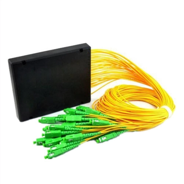
Shop the Smart Switch collection from Platinum Imports Inc: supplying a wide range of products for Barbados homeowners and businesses seeking to outfit or upgrade their kitchens, bathrooms, plumbing, and electrical fixtures. Shop online or visit our air-conditioned showrooms in Designers Hub and. We lead the industry in optical switch technology, delivering the lowest insertion loss (0. 2 dB), fastest switching speed (10 ns), broadest wavelength range (300–2400 nm), widest fiber compatibility, highest optical power handling (50 W), and space-qualified reliability. Backed by over 25 years of. Since we are the longest-standing security system provider in Trinidad, we already know which companies provide the best equipment. We are partners with Hikvison, Seco-Larm, DSC, Kantech and VDS - leading security equipment manufacturers. We are committed to continuously strengthening our brands and. What is an optical switch? An optical switch, also known as an optical line switching device (automatic switching type optical patch panel), is a device that enables the network to be always connected. Any communication protocol (Ethernet, ATM, etc. ) can. Control your lights from anywhere with the TP-Link Kasa Smart Light Switch—easy scheduling and voice control built-in.
[PDF]
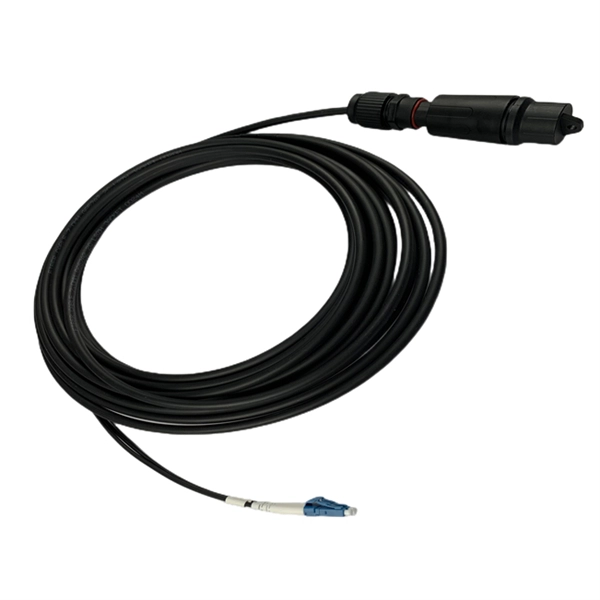
Bulk purchases typically come with discounts, making it more cost-effective for large-scale projects. Conversely, single or small quantity orders may incur higher per-unit costs. As of recent market analysis, the price range for OPGW cables is generally between RMB 10,000 to RMB 30,000. Fiber-optic cable materials typically cost $1 to $6 per linear foot, depending on fiber count and cable type. Commercial building installations with 100-200 network drops generally range from $15,000 to $30,000. Single-mode fiber costs less per foot than multimode fiber, but it requires more. Large core fibers from Fibercore. Highly customizable designs with a wide range of coatings available. Offering unique properties and benefits for different types of use, 8 core armoured cable Fiber Optic om3 multimode. TMT GLOBAL Fiber Optic Cable offers a high-quality multimode 8. Large core multimode optical fiber with core diameters from 10 ~ 2000µm provide ease of alignment and enable light/laser transmission with high power efficiency. A wide variety of silica core and silica clad optical fibers to cover a broad spectrum of wavelength ranges from deep ultraviolet (DUV). 20-meter hdmi 2. 0v fiber optic cable designed for high-resolution video transmission. Fiber Visual Fault Locator,10KM VFL Fiber Optic Cable Tester,Network Fiber Cable Test Fiber Light. 5m mtp 10gb 50/125 om3 multimode pvc fiber optic cable - aqua.
[PDF]

A single strand of glass fiber, called single-mode fiber, is used to transmit single-mode or light beams. It can transmit higher bandwidth than multimode fiber but requires a light source with a limited spectral range. There are mainly two types of optical fibers, single-mode optical fiber, and multimode optical fiber, which differ in the way light propagates. The latter is used for short-distance transmission, while the former is typically used for long-distance signal transmission. Please refer to the article. Single fiber modules (BiDi) use one fiber for both transmitting and receiving data. This saves space and money. Dual fiber modules use two fibers. They are easier to set up and give steady communication. Single-mode optical modules are best for long distances and fast speeds. Modes are the possible solutions of the Helmholtz equation for waves, which is obtained by combining. Optical fiber transmission is based on the principle of total internal reflection, where light signals are transmitted through a thin glass or plastic fiber with a core and cladding. The core has a higher refractive index than the cladding, causing the light signal to be reflected back into the. OS1 single mode fiber optic cables are made with a single mode fiber core, which means that they have a very small core diameter of 9 microns. Each type serves distinct applications based on its light transmission characteristics. Very small core (~8–10 µm). Carries one light path (mode).
[PDF]
A 3 × 3 all-optical interconnecting switch using three quantum dot semiconductor optical amplifier assisted Mach-Zehnder interferometers (QDSOA-MZI) has been designed. It can transmit input data to any outpu.
[PDF]
Glass fiber and plastic fiber is fragile. When individual fibers break, light transmission and uniformity are reduced. After the first few fibers break at a stress point, a chain reaction occurs, hastening t.
[PDF]

Receiver sensitivity is the lowest optical power level at which an optical receiver can successfully decode data with acceptable bit error rates (BER). It's a core parameter in optical transceiver specifications, indicating the module's capability to detect weak incoming signals. The standards body governing the application sets this specified BER. For example, SONET specifies that the BER must be 10 -10 or better. What Is BER? The bit error rate (BER) measures the data transmission precision within. Receiver sensitivity stands as a critical parameter impacting an optical transceiver's functionality. It denotes a module's capability to function in challenging environments and aids network operators in determining the system's maximum reach or link margin. Lower receiver. Among a group of optical receivers, a receiver is said to be more sensitive if it achieves the same performance with less optical power incident on it. The performance criterion for digital receivers is governed by the bit-error rate (BER), defined as the probability of incorrect identification of.
[PDF]
6Wresearch actively monitors the Palau Fiber Optics Cable Market and publishes its comprehensive annual report, highlighting emerging trends, growth drivers, revenue analysis, and forecast outlook. Our insights help. Est. Freight Cost? date (-30 days from arrival). Click here to find out more. Buyers typically pay for fiber optic cable by length, fiber type, and installation complexity. Main cost drivers include cable grade (indoor vs outdoor, armoured), distance, and labor for trenching, splicing, and termination. This guide presents ranges in USD and practical price estimates to help. CRU provides comprehensive, accurate and up-to-date price assessments and research reports for bare optical fibre across various key regional markets, combined with insights into the factors and events affecting markets. How does 6W market outlook report help businesses in making decisions? 6W monitors the market across 60+ countries Globally, publishing an annual market outlook report that analyses trends, key drivers, Size, Volume, Revenue, opportunities, and market segments.
[PDF]
Fiber testing is the process of verifying the performance of optical fiber cabling. This process includes a range of tests and measurements such as insertion loss, optical return loss, and fiber length. It encompass.
[PDF]

Contrary to popular belief, fiber optic cables do not contain copper. Instead, they consist primarily of glass or plastic fibers that transmit data using light signals. These fibers are surrounded by protective coatings made of materials such as polymer or epoxy resin. Fiber optic cables are designed to provide high-speed, no-signal-loss, and EMI-free communication in telecommunication, powergrid, datacenter, broadband, and industrial applications. Each optical cable is constructed using a precise combination of optical fibers, strength members, buffer tubes. Fiber optic cables use pulses of light through ultra-pure glass or plastic fibers to carry information rather than electrical signals. Cladding: Lower refractive index layer reflecting light back into. You might wonder if there's copper inside fiber optic cables. It's not a yes-or-no answer. So, it's about knowing the different types. Its primary method of data transmission relies on light signals traveling through glass or plastic fibers, rendering copper conductors unnecessary for that purpose. Fiber optic cables have revolutionized data transmission. The two core material technologies used in almost all cables are fiber optic, and copper wiring.
[PDF]

This helps keep fiber optic cables safe from harm and signal problems when you put them in. Use the right lubricant. Follow the rules for tension and bend radius. Try new methods like air blowing. Use smart. Fiber optic cable is surprisingly strong, durable and pliable; however, several best practices should be followed to ensure a successful cable installation. This article explores recommendations for pulling and installing fiber optic cable. This makes sure the cable pull is smooth and safe. Use smart monitoring devices. The Future Ready Solutions Tools & Test. A duct is available from point A to point B, a pull tape is blown in, a fiber optic cable is attached to it and the cable is pulled through the duct. Sounds simple, doesn't it. Recent observations and conversations with more than a few people in the fiber optic business have indicated. Route plan to ensure the duct run maintains the minimum bend diameter of the cable. For more information and all recommendations for installation, refer to Corning Optical Communications Standard Recommended Procedure SRP 005-011, "Duct Installation of Fiber Optic Cable". more Route plan to ensure.
[PDF]

The main components of a splice box are the splice cassette that picks up the fibers and their reserves, and the front panel which contains different connectors for transmitting signals via copper or fiber optic cables. A splice box (also known as splice distributor) is a housing in which fiber optic cables begin or end. Fiber optics are fanned out in splice boxes that are situated at the end of fiber optic transmission paths. It typically consists of two parts: an outer housing and an internal structure. In this response, we will focus on the. The FSB series of indoor wall mount enclosures are designed for centralized splice-only applications. These boxes are well suited as optical cable splice collection points for DAS (Distributed Antenna Systems), MTU (Multi-Tenant Unit) commercial business applications, and MDU (Multi-Dwelling Unit). Fiber optic splice closures permanently connect two fiber optic cables together and have a splice that protects the components. The optical cable connection part, that is, the optical cable joint, is the part that protects the connection between two or more optical cables by the optical cable. Splicing refers to the permanent connection of two optical fibers to form a continuous optical connection.
[PDF]

An armored optical cable is a type of fiber optic cable reinforced with a protective layer—usually corrugated steel tape (STA) or steel wires (SWA) —to shield the internal fibers from external threats such as crushing, rodent bites, moisture, and harsh installation conditions. With a durable protective layer, they are ideal for harsh or high-traffic environments. This article explains what armored fiber cables are, their key. Every optical fiber cable project faces the same critical question: should you choose an armored cable or a non-armored one? At first glance, the choice may look simple. Armored cables appear stronger, non-armored cables are cheaper. But the real decision is not that easy. The wrong choice can: Or. With the increasing demands on high-performance connectivity, for many buyers, choices boil down to two quite popular options: the outdoor armored fiber optic cable and the standard optical fiber cable. In this blog post, we'll explore the advantages and disadvantages of. Armored and non-armored fiber optic cables are engineered for different levels of mechanical protection, environmental resistance, and installation conditions. You select between them based on route exposure, rodent risks, burial requirements, tension loads, and overall ODN architecture. An under-armored cable in a harsh environment leads to fiber damage, network outages, and costly repairs. Over-specifying armored cable where standard cable suffices.
[PDF]