The global fiber optic industry is entering a new pricing cycle. Over the past several months, upstream material costs and supply chain constraints have pushed fiber prices upward, directly impacting cable assemblies, patch cord production, and passive optical components. For distributors, telecom. Since early 2026, the fiber optic cable price has been rising at an extraordinary pace. In some cases, suppliers only guarantee quotations for the same day, and in extreme situations even half-day quotations are appearing in the market. For many professionals who have worked in the optical. See why G. 652D optical fiber prices are rising in 2025–2026, how FTTH cable budgets are affected, and what procurement teams in Europe, Latin America, Africa and the Middle East can do to manage risk. From late 2025 into 2026, global fibre optic prices have increased sharply and across the board — standard single-mode, bend-insensitive grades, and in turn pre-terminated. In 2026, the optical fiber cable industry stands at a pivotal crossroads. After years of market adjustments, ordinary optical fibers are witnessing a 15% price rebound since May 2025, with carrier prices (carrier procurement prices) expected to follow suit. Standard single-mode G. 652D fiber, bend-insensitive G. 657A2 grades have all seen dramatic increases.
[PDF]
Fiber testing is the process of verifying the performance of optical fiber cabling. This process includes a range of tests and measurements such as insertion loss, optical return loss, and fiber length. It encompass.
[PDF]

Fiber optic loss calculation formula: Total link loss (LL) = Cable attenuation + Connector attenuation + Fusion attenuation [Note: If there are other components (such as attenuators), their attenuation values can be added]. Intrinsic Optical Fiber Losses comprise of absorption loss, dispersion loss and scattering loss caused by the structural defects. The detailed information about these optical losses and how to reduce them are. Calculate fiber optic signal loss based on cable length, attenuation, and connector losses. Determine cable loss, connector loss, and total system loss in decibels (dB) to assess signal quality and repeater requirements. Fiber optic loss is calculated in two parts: cable loss and connector loss. This calculator determines fiber loss based on input power, output power, and the length of the fiber optic cable. In summary, fiber optic loss is. Use this worksheet to input values for all variables that will impact your system's performance. After entering your values, please ensure you click the 'Calculate Link Loss' button at the bottom of the page to generate your total link loss. This step is necessary to see if your system falls within. Optical fiber loss is a term for signal loss affecting transmission reliability. Optical fiber loss is.
[PDF]

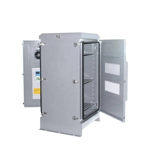
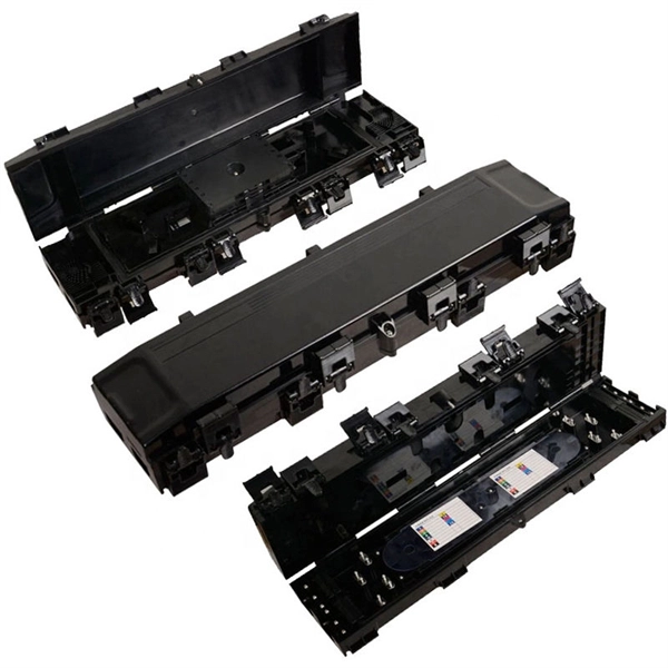
The main components of a splice box are the splice cassette that picks up the fibers and their reserves, and the front panel which contains different connectors for transmitting signals via copper or fiber optic cables. A splice box (also known as splice distributor) is a housing in which fiber optic cables begin or end. Fiber optics are fanned out in splice boxes that are situated at the end of fiber optic transmission paths. It typically consists of two parts: an outer housing and an internal structure. In this response, we will focus on the. The FSB series of indoor wall mount enclosures are designed for centralized splice-only applications. These boxes are well suited as optical cable splice collection points for DAS (Distributed Antenna Systems), MTU (Multi-Tenant Unit) commercial business applications, and MDU (Multi-Dwelling Unit). Fiber optic splice closures permanently connect two fiber optic cables together and have a splice that protects the components. The optical cable connection part, that is, the optical cable joint, is the part that protects the connection between two or more optical cables by the optical cable. Splicing refers to the permanent connection of two optical fibers to form a continuous optical connection.
[PDF]

Optical connectors are the physical interface that links an optical device to a fiber optic cable. Fiber optics are used in many applications, including medical imaging, automotive, military, industrial, and commercial (e., telecommunications). Each of these. Many people ask the same question: Can you use a fiber optic cable with an RJ45 port? The short answer is no - RJ45 connectors are designed for electrical Ethernet signals, while fiber optics transmit light pulses through glass or plastic. However, modern networks often combine both technologies. An optical fiber connector is a device used to link optical fibers, facilitating the efficient transmission of light signals. An optical fiber connector enables quicker connection and disconnection than splicing. They come in various types like SC, LC, ST, and MTP, each designed for specific. Proper connection of fiber optic cables is essential to harness these benefits fully, as even minor errors can lead to significant performance issues like signal loss. This article will guide you through the necessary tools, materials, and methods on how to connect fiber optic cables effectively. Most SFP fiber optic modules use LC connectors, while SC connectors are mainly found in legacy networks and MPO/MTP connectors are used for high-density cabling rather than directly on standard SFP modules. FC FO LC connectors for fiber optic.
[PDF]
TendersOnTime, the best online tenders portal, provides latest Mexico Optical Fibre tenders, RFP, Bids and eprocurement notices from various states and counties in Mexico. com offers an unmatched database of Optical Fibre Cables tenders from Mexico, more than any other platform. Daily, new procurement opportunities. Volza's Big Data technology scans over 2 billion import shipments on over 20 parameters to Buyers who are a perfect match and most likley to work with you. According to Volza's Fiber Optical Cable Import data of Mexico, there are a total of 1,654 Fiber Optical Cable Importers in Mexico, importing. Are you searching for the latest Fiber Optic Cable Tenders from trusted sources across the globe? Tender Impulse is the go-to tender website for businesses seeking verified and timely updates on public tenders, government tenders, and business tenders in a wide range of sectors. With our smart. The company offers training with expert engineers, both virtually and in-person, focusing on fiber optic cable installation and network design. They also manufacture and sell products for fiber optic networks, emphasizing their expertise in comprehensive solutions. According to Volza's Mexico Import data, Mexico imported 9,201 shipments of Fiber Optic Cables during Mar 2023 to.
[PDF]

Fiber optic pigtails are short, single, or multi-strand pieces of optical fiber cables with a connector on one end and exposed fiber on the other end. They are typically used to terminate fiber optic cables and connect them to patch panels, equipment, or other termination points. Fiber pigtails are simple in appearance, yet essential in function. Despite this ubiquity, they remain a source of confusion for procurement teams and junior installers alike—especially when it comes to connector type selection, polish type, and the tradeoffs between mechanical. Fiber Optic Pigtails, also known as pigtailed fibers, consist of an optical fiber connector and a section of optical cable. Characterized by having an optical fiber connector on one end and a bare fiber end on the other, they are primarily used to connect optical transceivers or other optical. A Fiber Optic Pigtail Complete Guide: As per types, connectors, and applications. In such contemporary fiber optic communication systems, low-loss, and connectivities, which have reliability, are crucial for not only maintaining high-speed but also high-quality data transmission. It is usually suitable for field termination using a mechanical or fusion splicer. Compared with quick termination or epoxy and polish connections placed on the field.
[PDF]
Corning's ClearCurve bend-improved single-mode fibers provide lower cost, superior installation speed and efficiency, and greater successful installations. 15dB ultra low IL fiber optic cable is less attenuation when bent or twisted compared with traditional bend insensitive fiber cables and this will make the installation and maintenance of the fiber optic cables more efficient. Their market growth is directly tied to the expansion of high-speed internet access and innovative data transmission methods. The global fiber optic cable market is. Gain in-depth insights into Bend Insensitive Fiber Optic Cable Market, projected to surge from $ 1. 5 Bn by 2033, expanding at a CAGR of 7. Explore detailed market trends, growth drivers, and opportunities. 5 USD Million in 2024. The Bend Insensitive Fiber Optic Cable Market CAGR (growth rate) is expected. GL FIBER focuses on optical fiber OEM production services, and is committed to providing customers with brand customization, personalized packaging design, optimal cable structure design, and the best packaging design for international container transportation. GL FIBER® provides the whole series.
[PDF]
These two categories define how light travels through the fiber core: Transmits a single light mode; very low attenuation; supports long-distance transmission up to 100 km or more. Transmits multiple light modes; higher dispersion; best for shorter distances. The most common distinction is between single mode vs multi mode fiber optic cable. There are many classifications of optical cables, due to the installation environment. It has stronger pressure resistance, corrosion resistance, greater tensile. In the landscape of network infrastructure, three primary cable categories dominate connectivity: twisted-pair copper cables, coaxial cables, and fiber optic cables. While copper-based solutions (such as Cat5e/Cat6 for twisted pair or RG-6 for coaxial) have long served as workhorses for local and. We'll cover single mode, multimode, and armored fiber cables below. Single mode fiber optic cable is made up of a small diameter glass or plastic core surrounded by cladding, which is a layer of reflective material. This small diameter core, typically around 9 microns in diameter, allows only one. There are two main types of fiber optic cables: single mode and multimode. Although they can do the same job in some instances, the different construction methods make each of them better suited to certain tasks and budgets.
[PDF]
It is a form of optical communication that relies on optical amplifiers, lasers or LEDs and wavelength-division multiplexing (WDM) to transmit large quantities of data, generally across fiber-optic cables.OverviewOptical networking is a means of communication that uses signals encoded in light to transmit information in various types of. These include limited range. The most common are, or commonly used in metropolitan, regional, national and international systems. Another variant of fiber-optic n. Components of a fiber-optical networking system include: • Fiber. Multi-mode or single-mode.• Laser or LED light source.•, also called mux/demux, filter, or prism. These can.
[PDF]

Mouser offers inventory, pricing, & datasheets for 8 Fiber Fiber Optic Cable Assemblies. Understanding the 8 core fiber optical cable price list is essential for businesses looking to invest in future-ready technology, as prices can vary significantly based on quality, application, and manufacturer. Whether you are a large corporation or a small enterprise, this guide will help you. Pricing (USD) Filter the results in the table by unit price based on your quantity. A tariff of 10% may be applied if shipping to the United States. A. Discover the perfect Optical Fiber addition with our 8 Core Optical Fiber Cable. Choosing OEM custom optical fiber manufacturing lets you specify details and order in bulk, which can drive cheap optical fiber cable pricing. This guide highlights cost-saving order strategies and reliable distributor. There are three primary types of 8-core fiber optic cables, each designed for specific performance needs, distance requirements, and application environments. The key differences between these types include core diameter, light source, transmission distance, bandwidth capacity, and typical use. An 8-core fibre optic cable is a high-density MPO (Multi-fibre Push-On) cable that integrates eight individual optical fibres within a single jacket. Featuring eight individual optical fibers protected by a durable metallic or non-metallic armor layer, these cables.
[PDF]

While nonarmored fiber optic cables don't require grounding due to their nonconductive properties, grounding is crucial when using armored fiber optic cables. Therefore, it is important to build a lightning protection system for fiber optic cables. How to Protect Fiber Optic Cable From Lightning? The major purpose of lightning protection systems is to conduct the high current lightning discharges safely into the Earth/ground. There are two main lightning. Fiber optic cable transmits data as light through glass or plastic strands, which means the fiber core itself carries no electrical current and requires no grounding. However, this does not mean every fiber optic installation is exempt from grounding requirements. Lightning-induced surges can travel through power lines, telecommunication lines, or nearby metallic structures and pose a. There are two main lightning protection grounding solutions in fiber networks, namely intermediate grounding and terminal grounding. These solutions use two ways of grounding for optical cable links both in domestic and foreign standards. However, because fiber optic cable has strengthened core, especially the direct-buried fiber optic cable has armoring layer.
[PDF]
The typical thickness of a glass core can range anywhere from 8-10 um (microns) for single-mode and 62. 5-50 um for multimode; these core sizes are the most prevalent ones utilized in the telecommunications industry. The core of a conventional optical fiber is the part of the fiber that guides the light. It is a cylinder of glass or plastic that runs along the fiber's length. The core is surrounded by a medium with a lower index of refraction, typically a cladding of a different glass, or plastic. The light is transported along the optical fiber via its smallest and most crucial component, which is called the core. However, they are composed of many components, each constructed from advanced materials to guarantee the quick and reliable transmission of data. So, let's break it down! The core is the primary part of a Fiber optic cable. It's responsible for. The 8 Core Multimode Outdoor Fiber Optic Cable is designed for high-performance data transmission in various outdoor environments, making it an ideal choice for telecommunications, networking, and data center applications. We supply single mode GYTS fiber optical cable and multimode GYTS fiber optic cable, fiber strand from 2 cores to 432 cores. A related GYTA type cable is available. This advanced cabling solution allows fast, secure data transfer and telecom over long distances. Understanding the components within a fiber optic cable enables.
[PDF]

South Korea Exports of optical fibres, optical fibre bundles and cables to Slovenia - data, historical chart and statistics - was last updated on July of 2024. 37 Million during 2022, according to the United Nations COMTRADE database on international trade. According to Volza's Fiber Optic Cables Import data of Slovenia, there are a total of 50 Fiber Optic Cables Importers in Slovenia, importing. In 2024, the Slovene market for optical fibers, bundles and cables was finally on the rise to reach $X for the first time since 2020, thus ending a three-year declining trend. Over the period under review, consumption, however, showed a pronounced descent. is a system integrator that offers services for optical and coaxial networks, highlighting its expertise in telecommunications infrastructure. Their comprehensive solutions are designed to support the operational success of businesses across various sectors. FMC Telco Group specializes. Fibernet is specialized in BtoB segment, serving businesses across all sectors operating in five main business segments: Highly skilled and motivated team is at your service, across the country or abroad to meet your requirements!. We offer a wide sales program cables and connectors and installation accessories. There is a virtual catalog of our latest offers. Our mission is to offer first-class quality for our clients, competitive prices and excellent service.
[PDF]

A novel method for aligning multi-core fibers (MCF) provides a systematic approach for MCF splicing in the lab, in cable factories, and in the field. Splicing fiber optic cable is an extremely important phase for making dependable, high-speed communication infrastructures. Regardless of the type of fiber network you're deploying, be it for telecom, enterprise data centers, or smart city infrastructure, fusion splicing provides the benefits of. This is where fiber optic cable splicing—the process of creating a permanent, high-performance join between two fiber ends—becomes critical. For network managers and technicians, a poor splice can lead to significant signal degradation, network downtime, and costly troubleshooting. At Turn-Key. W. Zheng, "Automated Alignment and Splicing for Multicore Fibers," in Optical Fiber Communication Conference/National Fiber Optic Engineers Conference 2013, OSA Technical Digest (online) (Optica Publishing Group, 2013), paper OM3I. However, realising its potential depends on one critical process, which is achieving ultra-low-loss fusion splices that maintain performance and. This guide reveals the secrets to fusion splicing with little fluff—just proven, straightforward techniques refined from years of work in the field. The guide provides the complete workflow, covering safety precautions, tool selection, fiber preparation, fusion operation, quality control, and.
[PDF]