The layer 2 switches prevent over-crowding of data packets in transmission links and access devices. · Layer Positioning: The data link layer (Layer 2) of the OSI model, realizing local forwarding of data frames based on MAC addresses. · Core Task: Establishing direct interconnections between devices within a local area network to ensure efficient communication within the same network segment. ·. The core layer is the backbone of the network. It provides a high-speed connection between different distribution layer devices. The distribution layer connects the access layer to the core layer. When designing a campus LAN, you may. In enterprise networking, the hierarchical three-tier model is divided into three distinct roles: access switches (which connect end-user devices to the network via Layer 2), distribution switches (which route inter-VLAN traffic and enforce security policies at Layer 3), and core switches (which. The core switch is the most important piece of hardware in this infrastructure, acting as the high-speed, central nervous system that ensures all parts of the network can communicate. The core switch functions as the central point of the entire network, forming the high-speed backbone for the. Distribution Layer: The distribution layer is an intermediate layer. Simply put, it's the kingpin that keeps your network humming. You may also want to know: Can a Nintendo Switch Play DS Games? ·.
[PDF]
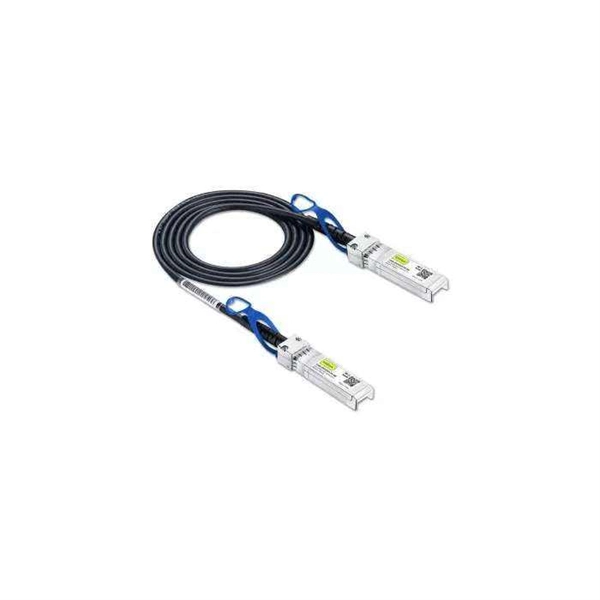
Actelis' fiber portfolio includes our managed layer 2 fiber switches and aggregation devices designed to extend connectivity over fiber, as well as our hybrid fiber-copper ethernet access devices that.
[PDF]
In a typical enterprise network architecture, the access layer switch is the first point of contact between end-user devices and the rest of the network. These switches connect endpoints such as PCs, printers, VoIP phones, and wireless access points, enabling user traffic to enter the LAN. It assists mainly in the switching of incoming and outgoing data packets to the right destination, as specified in MAC. In this layer, the layer 2 switches are installed to distribute the data packets to the addressed group of access devices. The layer 2 switches prevent over-crowding of data packets in transmission links and access devices. Wireless access points are also connected here and provide further access. FortiSwitch units distribute the ports to plugs. This layer serves as the network's outermost boundary and the gateway through which all data must pass. This layer is primarily composed of devices like access switches and wireless access points.
[PDF]

Normal WDM (sometimes called BWDM) uses the two normal wavelengths 1310 and 1550 nm on one fiber. Coarse WDM provides up to 16 channels across multiple transmission windows of silica fibers. Dense WDM (DWDM) uses the C-Band (1530 nm-1565 nm) transmission window but with denser. In fiber-optic communications, wavelength-division multiplexing (WDM) is a technology which multiplexes a number of optical carrier signals onto a single optical fiber by using different wavelengths (i., colors) of laser light. This guide delves into the principles, types, applications, and future trends of WDM. The concept involves sending multiple independent data streams down a single strand of fiber, much like transforming a single-lane road into a. Abstract Wavelength division multiplexing or WDM allows the combining of a number of independent information-carrying wavelengths onto the same fiber, because of the wide spectral region in which optical signals can be transmitted efficiently. This chapter addresses the operating principles of WDM. 📦 For purchasing, use the RP Photonics Buyer's Guide for wavelength division multiplexing. It provides an expert-curated supplier directory, buyer-focused technical background information, and structured selection criteria to support professional procurement decisions. WDM allows communication in both the directions in the fiber cable. In WDM, the optical signals from different.
[PDF]

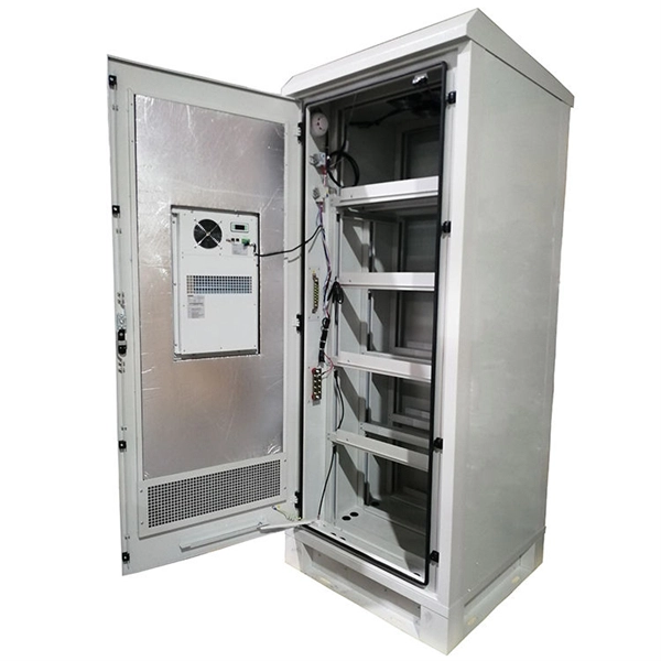
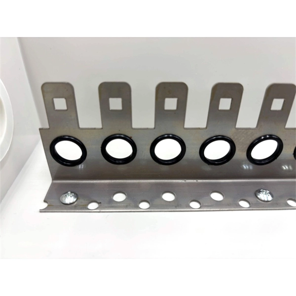
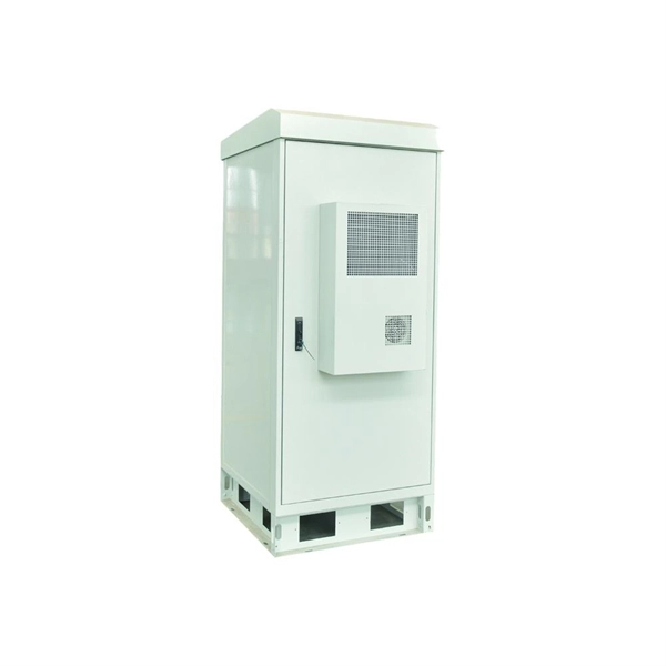
Cable Trays* — Max two 24 in. (610 mm) wide by max 6 in. (151 mm) deep open-ladder cable tray with channel-shaped side rails formed of 0. 54 mm) thick aluminum or min 0. In practice, cable tray dimensions are a system of interrelated measurements —width, depth, length, and material thickness—that directly affect cable fill compliance, heat dissipation, structural loading, and long-term expandability. From an engineering standpoint, cable tray dimensions are not. Perforated Cable Tray System expertly constructed from high-grade stainless steel, offering exceptional durability and resistance to corrosion. With side height 100mm. A properly designed and installed cable tray system will provide. Studs — Wall framing to consist of wood studs or channel shaped steel studs. Wood studs to consist of nom 2 by 4 in. Additional studs shall be used to completely frame. Best Size: Here, deep trays (75mm to 150mm) are used since power cables are typically thick and heavy. Data cables, such as your Wi-Fi or computer ones, are extremely sensitive. They do not get hot; however, they do not like to hang or sag. In case a data cable folds in an excessive manner, the. ect the minimum bend ra-dius for cables as they exit the bottom of the cable tray. A rung spacing of 6 to 9 inches (150 to 230 mm) is preferable when the cable tray cont d for instrumentation and control applications that require additional protec eferred to support and protect numerous small.
[PDF]

An Optical Splitter, also known as a beam splitter, is a passive optical device that divides a single input optical signal into two or more output signals. Conversely, it can also combine multiple signals into one. Knowing the difference between a splitter and an optical coupler helps you build better networks. You make your network work better when you pick the right device for each job. You can connect many users to one port with 1:n or 2:n splitters. By dividing a single optical signal from a central Optical Line Terminal (OLT) into multiple outputs for Optical Network Terminals (ONTs) at users' homes, splitters eliminate the need for dedicated fibers to each residence—slashing infrastructure costs while scaling network reach. This guide. In a Passive Optical Network (PON), a single optical fiber carries massive amounts of data using light. Signal Input: The fiber splitter receives the optical signal from the upstream network node and enters the splitter through the input fiber. Signal Distribution: Inside the splitter, according to the design structure and different. Splitters are passive optical devices that divide or combine optical signals, and they come in various types, including power splitters, uneven splitters, and wavelength-division multiplexing (WDM) splitters. Each type serves specific applications, enabling efficient use of optical infrastructure.
[PDF]
Switches in this layer are called access switches. In other words, an access switch forwards traffic between connected devices and the rest of the LAN. The following image shows a network that contains. The access layer is where endpoints (such as phones, laptops, video-conferencing sets, printers, IoT sensors, IP cameras, and servers) are primarily connecting to the network. FortiSwitch units distribute the ports to plugs. Access layer switches are primarily deployed in Layer 2 mode in the data center. A Layer 2 access topology provides the following unique capabilities required in the data center: VLAN extension—The Layer 2 access topology provides the flexibility to extend VLANs between switches that are connected. It contains three layers: core, distribution, and access. The core layer is the backbone of the network. It provides a high-speed connection between different distribution layer devices. The layer 2 switches collect the data from core switches, identify the type of data packet and the address of the access device. Further, the data packets are forwarded to the addressed group of.
[PDF]
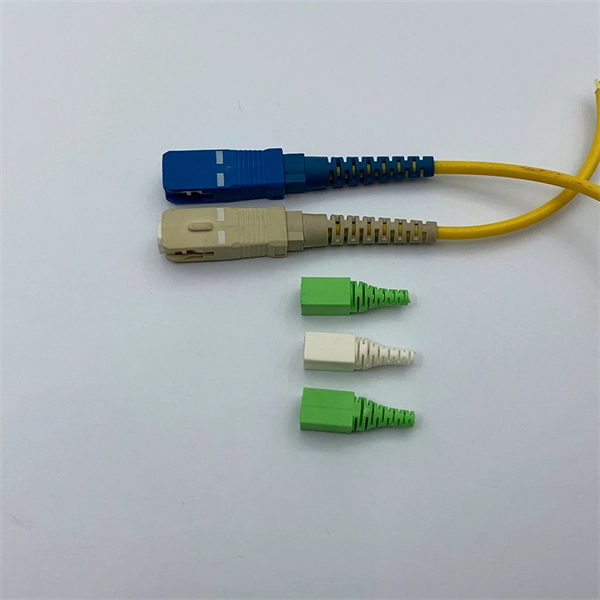
The protective outer layer, often called the jacket, surrounds the entire fiber optic cable. This layer is typically made from durable materials such as plastic, designed to protect the fragile core and cladding from external damage. Different types of cable are used for fiber-optic communication in different applications, for example long-distance. A fiber optic cable consists of five basic components: the core, the cladding, the coating, the strengthening fibers, and the cable jacket. When searching for a fiber optic cable, we need to pay attention not only to the connectors, such as SC to ST fiber cable, LC to SC fiber patch cable, or SC to. Fiber optic cables are made primarily of ultra-pure glass, specifically silicon dioxide (silica), the same compound found in quartz and ordinary sand. Each fiber is thinner than a human hair, yet it carries data as pulses of light across enormous distances. The materials are chosen for their clarity, flexibility, strength, and durability. What is Optical Fiber? Optical fiber consists of flexible glass or plastic strands engineered to transmit light. Manufacturers produce these fibers through a.
[PDF]