The soft starter wiring diagram typically includes information about the power supply, motor connections, control circuit, and bypass arrangement. It helps in understanding the complete wiring arrangement and makes it easier to troubleshoot any potential issues. See Technical Data TD03900001E. We are guided by our commitment to do business right, world's most urgent power management challenges. A proper wiring diagram is crucial to ensure the soft starter functions effectively and protects the motor from any kind of damage. Whether you're a professional electrician or a DIY enthusiast, this detailed wiring diagram and installation guide will help you understand the c. more. Soft starters are widely used to reduce the current surge when devices are started and to provide ramped acceleration to motors. The use of soft starters can reduce energy costs by up to 15%, as well as providing protection from damage caused by voltage sags or electrical faults. Connecting the soft starter to a wye motor inserts the SCRs directly in the line wiring, referred to as "In Line" wiring. If the motor is hard. If you're looking to install a soft start system in your electrical setup, it's crucial to understand the wiring diagram that goes along with it. A soft start system is designed to gradually increase the voltage and torque to a motor, reducing the initial inrush current and protecting both the.
[PDF]
The 6 terminal junction box wiring diagram provides a visual representation of how the various wires and connections should be made within the box. It shows the layout and arrangement of the terminals, as well as the color coding and labeling of the wires. Hey, in this article we are going to see the Single Phase Distribution Box Wiring Diagram and Connection Procedure. A distribution board or distribution box is where the main power supply is distributed to multiple loads. It provides a quick and easy reference guide to understanding the meaning behind each symbol. These symbols can represent different electrical components, such as switches, resistors. This technical article aims to take you on a journey through the fundamental terminals and other connecting elements of wiring diagrams and electrical schematics and to delve into the minute intricacies of the components that form them. From the familiar male and female terminals that form the. An electrical panel box, also known as a breaker box or a distribution board, is a crucial component of any electrical system. Whether you're an electrician or a DIY enthusiast, this guide will help you understand the basics of home electrical distribution. more Welcome to our. The Engineering Base terminal block diagram is a special template showing information about terminal blocks, terminals and their accessories. There are two methods for creating a terminal block.
[PDF]

Simple 3-phase distribution board wiring diagram for home use, showing safe connection of power supply, breakers, neutral, and earth for residential electrical systems. Hey, in this article we are going to see the Three (3) Phase Distribution Board Wiring Diagram and Connection Procedure. The three-phase distribution board is used to distribute power to the three-phase loads and circuits such as three-phase motors, three-phase machinery, three-phase to. A distribution board, also known as a DB box, is like the central hub of an electrical system. It contains multiple circuit breakers and connects various electrical circuits to ensure the safe flow of electricity throughout the building. Unlike single-phase systems, where power is distributed using. When it comes to understanding the basics of electricity and wiring, a wiring diagram of a three phase distribution board is indispensable. This diagram shows how electricity is distributed in a home or building and helps you identify which connections should be made when constructing, modifying or. Welcome to our channel! In this video, we'll walk you through the process of wiring a home distribution box with a detailed connection diagram. Whether you're an electrician or a DIY enthusiast, this guide will help you understand the basics of home electrical distribution. These setups typically provide 240V for most applications, but it's crucial to follow the proper configuration to prevent hazards.
[PDF]
The following wiring diagram shows the installation of a 60A subpanel for both 120V and 240V. You may use the current rating according to the system requirement i. 50A, 60A, 100A, 150A and so on. We have used 60A for illustration purposes only. Click image to enlarge. Primary distribution systems consist of feeders that deliver power from distribution substations to distribution transformers. A feeder usually begins with a feeder breaker at the distribution substation. Many feeders leave substation in a concrete ducts and are routed to a nearby pole. At this. An electrical sub panel, also known as a sub distribution board or sub circuit breaker panel, is a smaller secondary panel connected to the main electrical panel in a building. It serves as an extension of the main electrical panel to distribute power to different areas or circuits within a. secondary unit substation is a close-coupled assembly consisting of enclosed primary high voltage equipment, three-phase power transformers, and enclosed secondary low-voltage equipment. We have used 60A for illustration. Installing a subpanel is best handled by a professional electrician, but if you're curious how it's done, here is a brief overview of how to install a subpanel breaker box. Equipment Identify the location where you're adding a second breaker box. This information will help as you consider a Sub-Panel and its size. Electrical Tips and Be Sure to.
[PDF]

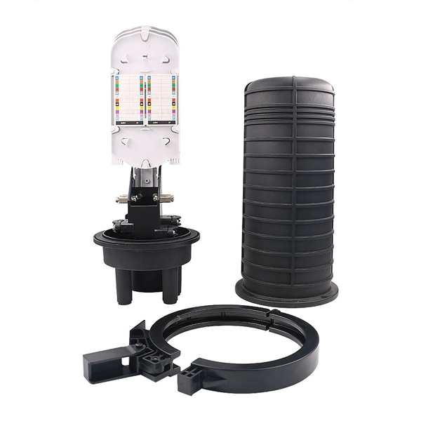
This guide covers the essential tools and step-by-step procedures for low-loss fiber optic cable repair. Understanding the causes and types of fiber optic cable damage helps detect issues early and determine when repair is needed. Construction Activities: Accidental damage during construction. Step1 : Identify the optical cabinet and network operating center, and find the fiber optic splitter. Step 2: Identify the splitter number. Step 4: Find the optical fiber port and cable sequence that leads to the user. 2) The. This complete guide covers everything from identifying causes of failure to advanced repair techniques, drawing on the latest industry standards and innovations. Whether you're a network technician, IT professional, or telecom operator, you'll find practical steps, tools, and tips to restore. If you accidentally break a fiber optic patch cord in your server room or in any of your switch gear, now you can repair it on the spot and get back up and running in minutes. Adhering to precise methodologies, we can mend impaired cables. By understanding these key elements and following the outlined steps, you can effectively repair fiber optic cables and maintain the high-performance network necessary for today's demanding communication needs. When it comes to ensuring nice network experiences for users, the condition of a fiber.
[PDF]
Ensure safe placement: install in dry, accessible areas with good ventilation and at appropriate height (typically ~1. Practice good wiring: secure grounding, neat cable management, proper insulation, and correct wire gauge and breaker size. The term “four wires” refers to three live wires and one neutral wire, designated as A|B|C|N|, with N representing the ground wire. The three live wires should be connected to the upper entry of the main switch in the explosion-proof distribution box, and the neutral wire should be directly. Learn how to wire a distribution box step by step! This video shows real on-site footage of electrical installation, demonstrating safe and standardized wiring methods used by professionals. This ensures compliance with NEC and simplifies troubleshooting. Include protection devices like breakers, fuses, and. Prevention of Electrical Hazards: Proper wiring ensures that electrical currents flow smoothly and safely through the circuits, minimizing the risk of electrocution and electrical accidents. Faulty wiring can result in electric shocks and even be life-threatening. Efficient Power Distribution: The. ormal operation due to poor manufacture quality. A paid repair will be provided if the warranty period expires. For any damage due to one of the following situations, a paid repair duct, please dispose the pro ype, a “R” is added after the Specification. For single row 20, and circuit 24, fter.
[PDF]
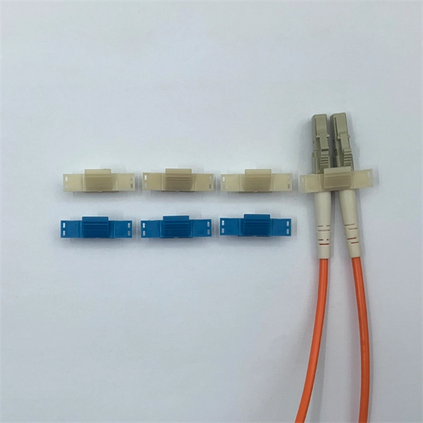
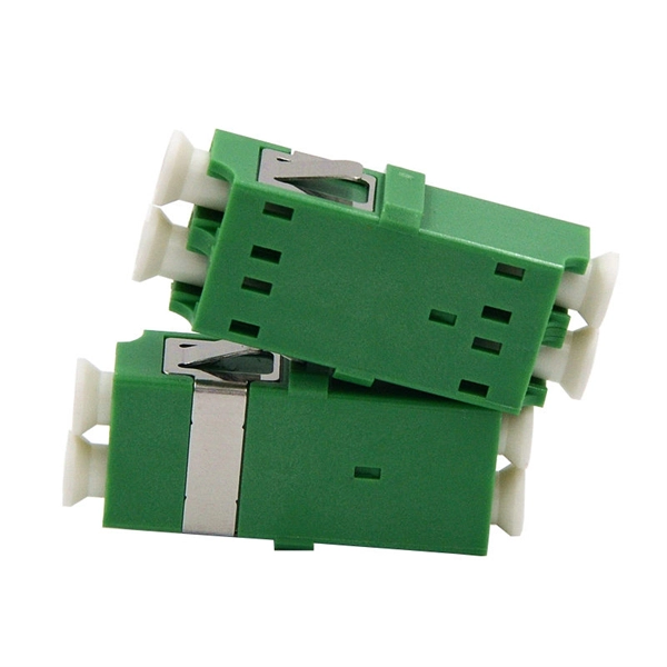
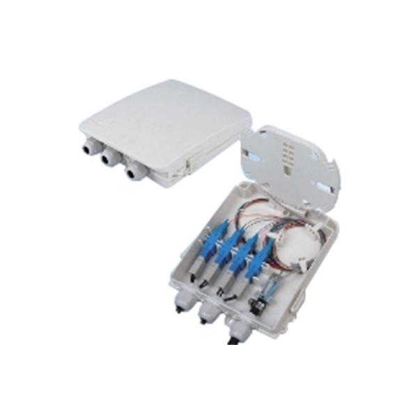
The 8 Port Fiber Access Terminal (FAT) is designed to connect feeder cables to subscriber drop cables for FTTH last-mile fiber connectivity; it can achieve direct or branch and terminal connection in FTTH or FTTB projects. FTB-SC8-WOPA type fiber optic terminal box is designed for FTTx application, which is cable to meet at least 8 users requirements. It can help splicing, splitting, storage and management with suitable space. Simple with light weight in design, special snap clip close system coinvent for user. ORCA® terminal optic box it is the best solution for indoor optical cable distribution or termination. The plastic case it is very light for a simple use. The FOTB fit the SC Simplex adapter (on request with ST and FC adapter). It is possible to buy the unloaded version (w/o Adapter) or the. Maximum capacity: 8 SC simplex, 8 LC duplex. The 8 port Fiber Distribution Box is sturdy in structure, lightweight in size, and easy to install. Built with high-density configurations and rugged materials, this MST box is perfect for installations in harsh environments like 4G/5G. The wall-mounted optic fibre termination box allows for easy organization of optic fibre cables (up to 4 fibres, depending on the installed adapters.
[PDF]
This guide breaks down everything you need to know about electrical distribution boxes in plain English. We'll explain what they are, the different panel types you'll encounter, NEC 408 requirements that govern their installation, and common applications for each type. The power distribution boxes deliver electricity from the main electrical main to other circuits. Several distribution boxes are designed for specific use in offices or industries. Main Distribution Board (MDB) 2. Each. Distribution boxes, also known as electrical distribution boards or panels, are pivotal components in electrical systems, ensuring the safe and organized distribution of electrical power throughout residential, commercial, and industrial environments. It receives power from the main electrical supply and divides it into separate circuits, each. Electrical control panels and distribution boxes are the backbone of modern electrical systems. From powering homes and industrial facilities to supporting medium-voltage infrastructure, these enclosures ensure safe, efficient, and reliable power distribution. Whether it's a small electrical.
[PDF]

In this complete wiring diagram guide, we will walk you through the step-by-step process of wiring a mag starter. We will explain the purpose and function of each component, provide clear diagrams, and offer expert tips to ensure a successful installation. Whether you're a beginner or an. For proper integration of an electromagnetic securing device, ensure the power supply matches the specified voltage–typically 12V or 24V DC. Incorrect voltage can cause malfunction or reduced holding force. Use a regulated power source to prevent current fluctuations that might trigger false alarms. Understanding the wiring diagram of a magnetic starter is essential for technicians and electricians who work with electric motors. This diagram provides a visual representation of the components and connections involved in the operation of the starter. Once you have everything ready, you can proceed with the installation process. Begin by determining the appropriate position for the magnetic lock on the door. Quick guide on how to wire an access control system with power supply, lock, and exit button. more Quick guide on how to wire an access control. Installing a magnetic door lock can be a cost-effective and reliable way to secure your doors. These locks use an electromagnetic current to keep the door securely closed, and they are commonly used in commercial and residential buildings.
[PDF]

Figure 1 is a diagram of the basic construction of both loose-tube and tight-buffer fiber optic cable. An optical fiber cable is a complex structure designed to protect fragile glass fibers that transmit digital data using light signals. This advanced cabling solution allows fast, secure data transfer and telecom over long distances. Understanding the components within a fiber optic cable enables. A fiber optic cable consists of five basic components: the core, the cladding, the coating, the strengthening fibers, and the cable jacket. When searching for a fiber optic cable, we need to pay attention not only to the connectors, such as SC to ST fiber cable, LC to SC fiber patch cable, or SC to. Optical fibers are circular dielectric wave-guides used to contain and transmit light over short or long distances. They consist of three elements as shown in Figure 1: a central core, cladding and a protective coating. Understanding its internal structure is essential to appreciate how it functions efficiently in various applications, from telecommunications to medical devices. The core is the. 3,260 optical fiber structure illustrations, drawings, stickers and clip-art are available royalty-free for download. Multimode all-media self-supporting fiber optic cable structure isolated on white. More specifically, we can say that it is a waveguide that has the ability.
[PDF]
This diagram shows how the RJ45 cable is connected to the PoE switch, allowing it to power devices such as IP phones and cameras. In this article, we will explore the wiring diagram for a PoE switch, which provides a visual representation of how the switch connects to various devices. Each device is represented by a. Do you want to set up a new computer network in your home or office? Chances are, you'll need a Poe switch wiring diagram. Not only do these diagrams provide all the information you need to install a network, but they also help make the process easier and more efficient. For those who don't know. A PoE Switch, also known as Power over Ethernet Switch, is a network device that allows users to power and connect devices such as IP cameras, VoIP phones, and wireless access points. In essence, a PoE Switch can be described as regular switch with added ability of Power over Ethernet which allows. PoE technology enables the transmission of both data and power over a single ethernet cable, simplifying network setups and eliminating the need for additional power sources. This is particularly useful in scenarios where devices like IP cameras, wireless access points, or VoIP phones need to be. Here, you can see the details, Keep the copper strips towards your face and count the pin number or pin position from left to right. The T568B also has a total of eight pins and sight different colors.
[PDF]
Whether you're an electrician or a DIY enthusiast, this tutorial will help you understand the fundamentals of wiring a distribution box for a residential setup. The diagram of the distribution board's wiring shows exactly how each circuit is wired and connected. What is Distribution Board? Distribution board. A distribution box is the heart of any electrical system. It takes the incoming power and safely distributes it to different circuits throughout your building. Whether in a home or an industrial facility, this box keeps your electrical setup organized, functional, and efficient. However, the key to. In this guide, we will break down the key elements involved in connecting the main power supply to your home, providing a clear path for a successful setup. We will focus on the critical parts of the system, from basic components to step-by-step assembly procedures. It serves as a central hub for distributing electricity throughout a building, ensuring that power is delivered safely and efficiently to all the required locations.
[PDF]

In the following tutorial, we will show how to wire 120V single-phase and 240V split-phase circuit breakers and loads inside a residential main panel. The figure below shows a typical breaker panel used for 120V and 240V circuits. Messy distribution boxes are dangerous and very hard to fix. You will learn to build a safe, efficient, and professional electrical system today. Circuit breaker wiring configurations involve organizing main switches, busbars. A breaker box, also known as a circuit breaker panel, is an essential component of any electrical system. It is responsible for distributing electricity throughout a building, ensuring that each circuit receives the proper amount of power. To understand how a breaker box works, it is helpful to. Each circuit is protected by a circuit breaker, a safety device that automatically shuts off power if it detects an overload or a fault. If you're looking to replace an old fuse box replacement or upgrade your home's power capacity, you'll be dealing with the load center or service panel. The distinction between 1P and 2P circuit breakers plays a pivotal role in determining the appropriate protection level for various circuits. When installing or troubleshooting a power distribution system, understanding how to correctly connect the main electrical supply to the control panel is crucial.
[PDF]
The Box Fill Calculator is an essential electrical installation tool that determines the maximum number of conductors, devices, and fittings that can be safely installed in electrical boxes according to National Electrical Code (NEC) standards. Calculate electrical box fill capacity and ensure NEC compliance for proper wire management and electrical safety. Click on any. Learn how to wire a distribution box step by step! This video shows real on-site footage of electrical installation, demonstrating safe and standardized wiring methods used by professionals. It serves as a central hub for distributing electricity throughout a building, ensuring that power is delivered safely and efficiently to all the required locations. The National Electrical Code (NEC) and Canadian Electrical Code (CEC) specify strict limits on how. In just a few steps you will find the wiring and assembly plan, including complete documentation in accordance with standards. This is the design philosophy which the browser-based distribution board configurator from Eaton is based on. Distribution board configurator for different types of. Hey, in this article we are going to see the Single Phase Distribution Box Wiring Diagram and Connection Procedure. And all the switching and protective devices are installed in the.
[PDF]
This video shows real on-site footage of electrical installation, demonstrating safe and standardized wiring methods used by professionals. more Learn how to wire a distribution box step by step!. Explosion-proof distribution boxes, vital terminal distribution equipment in power systems, play a crucial role in controlling and protecting industrial electricity in hazardous environments. Given their ubiquity, let's delve into the installation and wiring of indoor distribution boxes today. Choose the right box based on environment (indoor/outdoor), load capacity, and durability. Check for proper IP/NEMA ratings and material quality. These panels are commonly installed in areas like detached garages, workshops, basements, or home additions to manage localized electrical loads. Whether you're an electrician or a DIY enthusiast, this guide will help you understand the basics of home electrical distribution. What is Distribution Board? Distribution board. Common NEMA ratings include NEMA 1 (for basic indoor protection) and NEMA 4 (for corrosion resistance). If your distribution box is installed outdoors and exposed to rain and sunlight, you need to select an electrical enclosure with a higher protection level, such as models with IP66 or NEMA 4.
[PDF]