Welcome to our step-by-step guide on installing cable trays! In this video, we'll explore the different types of cable trays available and provide detailed instructions for their installation. Whether you're an experienced electrician or a DIY enthusiast, this. Whether you're building a commercial setup or upgrading an industrial plant, proper cable tray installation ensures neat wiring, safe access, and easy maintenance. But before you lay the first tray or clamp down a single cable, you need a solid plan. This guide breaks down the process step by step. Installing a cable tray system requires careful planning to ensure it can support the weight of the cables and adheres to electrical safety codes. Here is a step-by-step guide on how to install a standard metal cable tray system (e., ladder or perforated type). more. The purpose of this article is to define the sequence and methodology for the installation of electrical cable trays, cable trunking, cable raceways and boxes, junction and pull boxes. The method gives details of how the work will be carried out and what health and safety issues and controls that. Cable tray systems are designed for easy installation and to accommodate power, communications, and signal cabling across a variety of applications. When installed and engineered properly, cable.
[PDF]
Proper planning for installing cable tray includes calculations based on loading, support systems, cable/wire fill and spacing, conductor types, securing of the cables and wire, and proper grounding and bonding are all important aspects of cable tray installation. How about organizing your wiring with a cable tray system? Smart move. Whether you're building a commercial setup or upgrading an industrial plant, proper cable tray installation ensures neat wiring, safe access, and easy maintenance. This guide covers the critical steps, from selecting the right electrical cable tray and performing accurate cable fill. Cable tray installation implies the construction of an electric road that will be safe. In order to get it right, installers are supposed to adhere to a plan that ensures that wires are kept cool and the building is stable. The beginning of success is to review the Bill of Quantities (BOQ) so that. Our solutions and products are made in the USA and our service and support can assist with any install or product selection questions that you may have. Here's what you'll learn: Planning: Assess cable requirements, calculate loads, and select the right tray system (ladder, trough, or wire mesh) based on factors like weight and environment. Proper installation of cables in trays is critical for maintaining an efficient and safe electrical system. This is why proper planning and execution are.
[PDF]
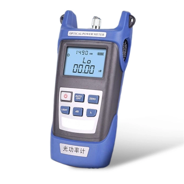
The normal recommendation for fiber optic cable is the minimum bend radius under tension during pulling is 20 times the diameter of the cable (d). While installers are aware of the fundamental importance of minimum bend radii, they often lack the practical know-how to systematically calculate bend radii under real installation conditions. Different fiber types, cable designs and load conditions each require specific bending radii calculations. This calculator helps you determine the minimum recommended bend radius for your fiber optic cable during installation and long-term use. Note: Some cables have. The calculator uses conservative routing multipliers, then compares the actual bend radius against the cable family minimum so you can spot risky turns early. Configuration type Cable family Installation phase Route style Route length (m) Used for bend density and overall planning context. Cable. To ensure optimal performance and long-term reliability, follow these industry-standard calculations: Copper Ethernet (Cat5e/Cat6/Cat6a): The standard rule of thumb is 4x the outer diameter of the cable. For shielded cables or thicker jackets, always consult the manufacturer's datasheet to prevent.
[PDF]
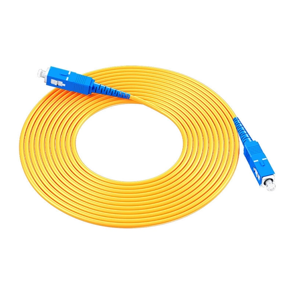
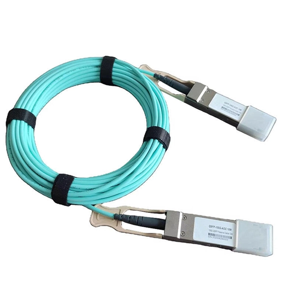
Basic — 1,000 ft single-mode run indoors with minimal termination: Cable $0. 00/ft, Permits $150, Accessories $100. Total ≈ $2,650–$3,100. 60/ft . Free Shipping with $189 Order. 100% Satisfaction Guaranteed. 30-Day Return Warranty Technical Support Live Chat. Pre-terminated Fiber Optic Cable is a hassle-free and reliable solution for realizing fiber connection without huge investment and complicated termination. Simply plug the cable to any. When you buy cables pre-terminated from Discount-Low-Voltage. com, you'll get value pricing and reliable performance. Our pre-terminated fiber optic cables save you the trouble and expense of terminating cables on site, expediting installations and reducing labor costs. 36dB/1000m ² Insertion Loss (1550nm wavelength) for pre-terminated butterfly drop cable with L > 200m: 0. They ensure the efficient delivery of audio, video, data, fiber internet, smart controls, and support HDMI. FS offers pre-terminated multifiber optic cable assemblies at wholesale price that save much installation costs and times for indoor/outdoor fiber optic cabling systems. Buyers typically pay for fiber optic cable by length, fiber type, and installation complexity. This guide presents ranges in USD and practical price estimates to help.
[PDF]
Here's a step-by-step guide to help you properly arrange fiber optic patch panels in a data center environment. Before installation, assess your network's current and future needs:. This guide outlines the key steps and considerations for effective cable management in fiber optic systems. Managing fiber optic patch cables requires strict adherence to technical standards due to the unique material properties of the cables. Even the most advanced optical transceivers can only perform at their peak when paired with properly installed, clean, and precisely managed fiber. Knowing the ins and outs on fiber patch cords and how they are important in server racks Glass fiber patch cords are very slim cables that are excellent at transmitting information quickly and in great quantity. It is essential when racks of servers are used, to maintain a strong and secure. In this configuration, a permanent link is installed between QuickNetTM Patch Panels in the switch/network cabinet and the server or storage cabinets. The most common, flexible, and upgradeable QuickNetTM Fiber Solution is shown in Figure 2, below: In this configuration, permanent links are. Patching fiber optic cable involves carefully splicing two ends together to repair a break or extend a cable run. Here's a breakdown of the process: Assess the Damage and Prepare: Carefully inspect the damage to determine if a patch is feasible. Severely damaged cables may require replacement.
[PDF]

This is a simple video showing how to install a 850nm fiber optic link using SFP transceivers between 2 10 Gigabit backbone switches. Covers transceiver inst. As a leading provider of fiber optic solutions, Weunion offers a wide range of SFP-compatible products, including optical transceivers, DAC/AOC cables, LC patch cords, and MPO/MTP assemblies. This guide explores the essentials of SFP connectivity, installation best practices, and how Weunion's. These transceiver modules are hot-swappable input/output (I/O) devices that plug into 100BASE, 1000BASE and 10GBASE ports (for SFP+), which connect the module port with the fiber-optic or copper network. This document contains these sections: The SFP transceiver modules are hot-pluggable I/O. An optical module is an optoelectronic conversion device that transmits data by converting electrical signals into optical signals. Common types of optical modules include SFP, SFP+, SFP28, QSFP, QSFP28, etc. Different types of optical modules have different performance parameters such as speed. The 1310 nm WWDM solution, 10GBASE-LX4, requires the use of a mode-conditioning patch cord on multimode fiber to achieve its specified range of operating distances. more Audio tracks for some languages were automatically generated. Learn more This is a simple. One of the most widely deployed optical solutions for short-distance 10G links is the multimode SFP+ transceiver, commonly referred to as a 10GBASE-SR module.
[PDF]
We calculate cable tray weight using the formula: Volume × Material Density. The calculation accounts for side rails, rungs, and cross-bars. Find the volume of the cable tray: This depends on the dimensions (width, height, thickness) and length of the tray. Multiply the volume by the material density: This gives you the total weight. Now, let's look at the specifics of Cable Tray Weight Calculation for each tray type. Channel trays are. The calculation of cable tray weight relies on the following formula: Weight (kg) = Material Density (kg/m³) × Total Volume (m³) To apply this formula, you need: Material type profoundly influences tray weight and suitability. 00 for bare tray weight. Used only when cover is selected. Used to estimate joints/couplers. Set to zero if unknown. Typical 200–300 mm spacing. rung bar. Height of the Cable Tray You Have: mm Weight Capacity of the Cable Tray You Have: kg/m RESULTS Total dia of all cables: 0. 00kg/m Width of all cables: 0. 00mm YOUR SELECTION ANALYSIS WIDTH CHECK: HEIGHT CHECK: WEIGHT CHECK: REMAINING CABLE. Values are applicable to all resin systems, where possible.
[PDF]

In this tutorial, I will show you how you can connect the Optocoupler to Arduino, read the data as Analog or Digital, and if necessary convert the analog values to digital, and how to reduce noise from the sensor. The Infrared Slotted Optical Optocoupler Module is a device that uses infrared light to transmit signals between two electrically isolated circuits. It consists of an infrared emitter (LED) and a photodetector (phototransistor) housed in a slotted enclosure. When an object passes through the slot. Slotted Optocouplers (Photo Interrupters) are very useful sensors, often included in Arduino projects to detect position of moving objects, measure speed of rotation, or linear motion, frequency of events, and many others. They are easy to use, but it is important to understand how they work, so. This tutorial is a comprehensive, practical guide to the Speed Sensor / Tacho Sensor (Slot-Type Optocoupler) (Leobot Product #245). Moreover, a simple application is programmed that shows how to wire and how to program an Arduino when working with the module. In this tutorial, the module is used as an “digital input board”. If you want to use the. In this project, I will talk about Phototransistor Optical Interrupter Switches (Opto Coupler) Module, how this module works and helps in determining the speed of a rotating object and finally I will show you how to Interface Optical Interrupter Switch Sensor with Arduino and measure the speed of a.
[PDF]
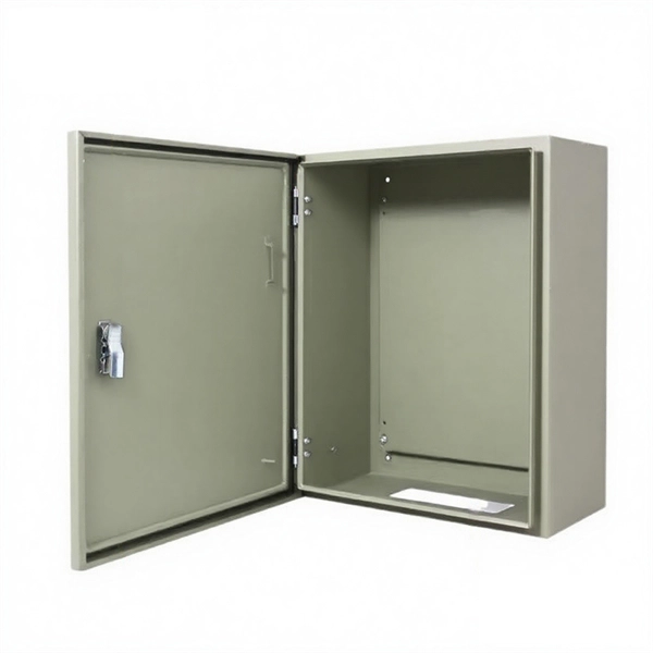
This video shows real on-site footage of electrical installation, demonstrating safe and standardized wiring methods used by professionals. Whether you are setting up a new telephone line or troubleshooting an existing one, understanding the basics of wiring is essential. In this article, we will explore the key components of a telephone line box and the. In this video, we'll walk you through the process of wiring a home distribution box with a detailed connection diagram. What is Distribution Board? Distribution board. mounted in OnQ Service Center Enclosures and come in several different telecom/video combinations; an example (6+8) is shown yle fittings for connecting incoming and outgoing cables. ve an 8 position 110 punch-down connector for incoming 4 ine service and 110 (8) position punch-down connectors. With the right wiring diagram, you can easily complete the job and get your outside phone box up and running in no time. If you're looking for a wiring diagram to help you install an outside phone box, then you've come to the right place. From there, the wiring is divided into separate lines for different areas of the house, such as bedrooms, living rooms, and kitchens. Each line is then connected to a.
[PDF]
00 Original price was: $285. Add an LC fiber optic connection to your Blackmagic Studio Camera, Teranex Converter, ATEM hardware, or any other professional device that supports SFP cages with. Help others learn more about this product by uploading a video! Looking for specific info? Would you like to tell us about a lower price? Found a lower price? Let us know. Although we can't match every price reported, we'll use your feedback to ensure that our prices remain competitive. 6G data rates support SD, HD, and 4K resolutions, and the fiber optic communication allows. FiberMall SFP+ Transceivers are hot swapping, cost effective modules supporting data rate of 6Gbps/8Gbps/10Gbps/16Gbps/32Gbps and up to 120km transmission. Learn more Spread the cost of your purchases over 3 to 24 months with an interest rate from 0. There's no fees if you pay on time. All set! You can manage payments in the Klarna app or website Down payment may be required. Klarna Monthly.
[PDF]

Professional Cable Tray Elbow Making | Metal Fabrication Tutorial Learn how to make cable tray elbows professionally with step-by-step guidance. This video shows metal fabrication techniques, DIY cable tray projects, and tips for perfect bends and joints. Whether you are a DIY enthusiast. The method for producing bridge bend elbows is as follows: Take a 90-degree cable tray bend elbow as an example, and apply the same principles for 45-degree bends accordingly. The length of the bottom side (bottom diagonal) after bending the cable tray should be equal to the width of the cable. This manual is designed to guide workers through the detailed production process of ladder cable trays, including the manufacture of horizontal elbows, tees, crosses, reducing bends, and vertical bends, with emphasis on precision, safety, and quality control. What's Involved in Producing Ladder. The bends, tees, crosses, risers and reducers of wire mesh cable tray can be easily and quickly made live at the project by using a bolt cutter. Since the jaws of the bolt cutter drags a layer of zinc across the cut end and forms a protective layer. When a wire cable tray is cut, the fact that a. How to bend 22. 5 DEGREE OF CABLE TRAY 3 LA. How to bend 90 degree of cable tray 3 line with the same distance :// • HOW TO BEND 90 DEGREE OF CABLE TRAY 3 LINE. Enjoy the videos and music you love, upload original content, and share it all with friends, family, and the world on YouTube.
[PDF]

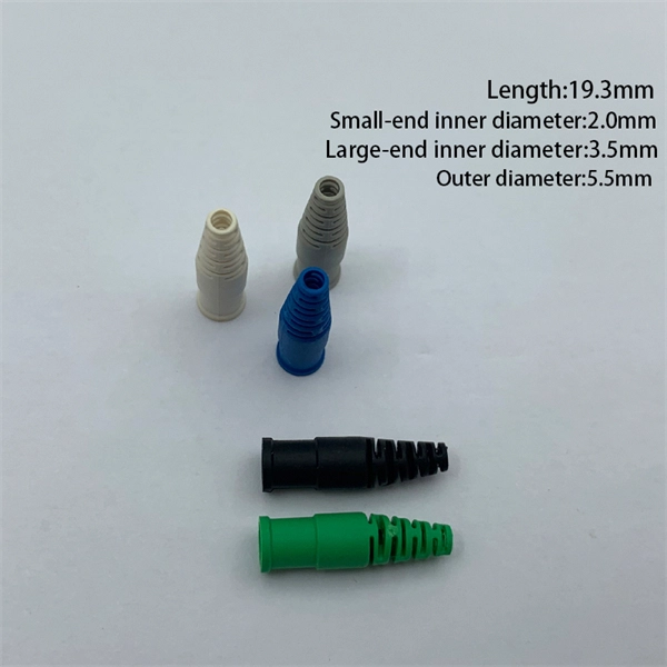
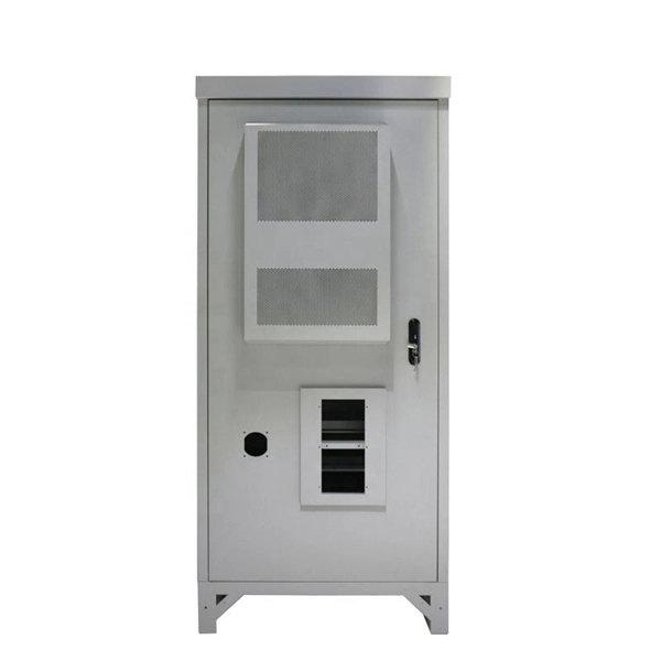
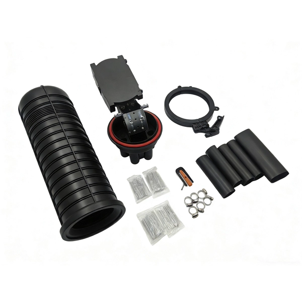
The compact 1 port ftth fiber termination box can hold 2 cores splicing, termination and coil up to 30 meters long for cable management in FTTH network. The 1 port fiber termination box is available for fiber optic cable coiling, it is great to connect optical cable and pigtail and protect fiber splices from damage. It is small, lightweight, and offers the function of fiber splicing, storage, and termination, mainly used in residential buildings. The maximum distance for single mode fiber optic cable can extend up to several hundred kilometers, making it ideal for long distance data transmission. One type of single mode fiber is known as “G. 652,” which is commonly used in telecommunications networks. Here are some general guidelines: 1. The shorter distance accounts for the. A fiber optic distribution box (FDB) is a protective enclosure for managing fiber optic cables. It organizes connections, splices fibers, and distributes signals in networks like FTTH (Fiber-to-the-Home) or FTTB (Fiber-to-the-Building). It acts as a central point for terminating, splicing, and distributing these cables, providing necessary protection and. The Fiber Optic Association, Inc. (FOA) was founded in 1995 to help develop the workforce to build the fiber optic networks to support a rapid expansion in communications and the Internet. The charter of the FOA was to promote professionalism in fiber optics through education, certification, and.
[PDF]
To set up your router for fiber internet quickly, connect the router to your fiber modem, access the router's settings via a web browser, and input the provided ISP credentials. Make sure to update the firmware, configure Wi-Fi security, and customize your network name for. In this guide, we'll walk you through how to connect a fiber optic cable to a router safely and efficiently. Why Use Fiber Optic Internet? Before diving into the setup, let's quickly recap why fiber optics are worth the effort: Lightning-fast speeds (up to 1 Gbps or higher). This article will walk you through fiber optic cable installation and how to configure your router settings to enjoy high-speed connectivity. With. The process to connect fiber optic cable to router requires careful attention to detail, but I'll walk you through every critical step with the precision and clarity you deserve. This comprehensive guide combines industry standards with field-tested practices to ensure you achieve a rock-solid. Setting up a fiber internet connection requires understanding key hardware components and following a specific connection sequence to establish your home network. This guide details the necessary physical and digital steps to connect your fiber line and activate your internet service. Here's a step-by-step guide to help you through it. Understand the Basics Before diving in, familiarize yourself with the components involved:.
[PDF]

Optical modules convert electrical signals into light to move data quickly and reliably in AI systems, enabling fast and smooth data processing. Using advanced optical modules boosts AI system speed and bandwidth, helping handle large data loads with low delay and high efficiency. Optical modules. Laboratory utilities: framework for communication with laboratory equipment and post-processing of data (opticomlib. You can install opticomlib using pip: or from source code: NumPy Compatibility: binary_sequence and electrical_signal now fully support NumPy protocols, allowing direct use with. The optical module serves as a crucial component in optical fiber communication systems, operating at the physical layer, which is the lowest layer in the OSI model. Its primary function is to achieve optoelectronic conversion by converting electrical signals into optical signals and vice versa. An. Learn about the components inside a coherent optical engine, what they do, and how they use modulation to send and receive data. Optical communications over metro, long-haul, and submarine networks once used simple direct-detect technology. That's no longer the case.
[PDF]

This article helps network engineers, field techs, and IT managers choose the right single-mode transceiver campus optics by tying IEEE Ethernet requirements to day-to-day deployment constraints: reach, budgets, DOM behavior, and operational limits. Huawei eKit offers a comprehensive series of pluggable optical modules in the Huawei eKit portfolio. The wide variety of modules gives you flexible and plug-and-play options for all types of interfaces. You will also get a practical checklist, common. Multimode and Singlemode optical modules differ in terms of fiber type, transmission distance, cost, and application scenarios. Understanding these differences is the first step in selecting the right module. This saves space and money. Dual fiber modules use two fibers. They are easier to set up and give steady communication. Its primary function entails converting electrical signals into optical signals. This assembly comprises a light source, such as a laser diode or a semiconductor light-emitting diode (LED), an optical interface, a. A single-mode receiver is an optical device that converts incoming light signals—carried over single-mode fiber (SMF)—back into electrical data. Unlike multimode receivers, which accept wider light beams from LEDs or VCSELs, single-mode receivers pair exclusively with laser-based transmitters.
[PDF]