This guide provides a complete framework for understanding, identifying, and planning MPO connector gender in data center environments. Visually, male and female MPO connectors are easy to distinguish: male connectors feature two alignment pins (PIN pins), while female connectors have corresponding holes instead of pins. An MPO connection is made between a male and female connector to make sure that there is proper alignment. Interfaces on active MPO equipment, such as transceivers are usually male, so any MPO trunk cable. In modern data centers and high-density fiber optic networks, MPO (Multi-Fiber Push-On) connectors have become an essential solution for achieving fast, reliable, and scalable connectivity. You will discover the physical distinctions between male and female connectors and how to develop a gender strategy for your infrastructure, which gender connects. Whether you're supporting parallel optics like 100G SR4 or densifying an optical distribution frame (ODF), MPO is now a cornerstone of network design. This article explains: And a practical checklist to design MPO systems that scale cleanly. If you only remember one thing: MPO is a multi-fiber. In MPO and MTP fiber connector systems, Male vs Female and Pin vs No-Pin describe the same core engineering attribute: the presence or absence of alignment pins on the MT ferrule. Unlike single-fiber connectors such as LC or SC, this distinction is not optional terminology but a mandatory.
[PDF]
Here at AFL we provide years of experience and excellent solutions for your hardware needs in both ADSS (All-Dielectric Self Supporting), OPGW (Optical Ground Wire) and SkyWrap cables. Please follow the links below for assistance in choosing your hardware. The aluminum Opti-LoopTM FOS for All Dielectric Self Support (ADSS) cable is available in 3 sizes. With more than one million units in service, Opti-Loop fiber storage systems lead the industry in quality and durability. All aluminum construction with continuous welds at crossbars and ends. Each. Also see our line of ADSS Fiber Optic Cable. © Copyright 2026 AFL. Our product experts are here to assist you. Get in touch with our team now. PLP transmission, distribution, substation, fiber optic, solar, and EV solutions protect and connect overhead electric power lines and communications networks. ADSS Anchor Tension Clamps are hardware fittings used to securely terminate and anchor ADSS fiber optic cables on poles or towers without damaging the cable. This is a type of self-supporting optical fiber cable that does not require any kind of support in distributing electricity from one point to another. As much as they may be independent, these cables are usually installed on poles and.
[PDF]
In STP, copper wires are first covered by plastic insulation. A metal shield, which consists of metal foil or braid, surrounds the bundle of insulated pairs. Where electromagnetic radiation is a serious issue, eac.
[PDF]

Fiber optic cable can be run anywhere from 300 meters up to 80 kilometers (roughly 50 miles) depending on the cable type, transceiver used, and network standard. For most enterprise or data center applications using multimode fiber, the practical limit sits between 300 m and 550 m. Fiber optic cable transmission distance is determined by two primary physical factors that affect signal quality as light travels through the fiber medium. The greater the distance, the greater. Many factors decide the fiber cable distance, but the key factors include the below six aspects. Attenuation First is the attenuation of the optical fiber. OM2 extends this to 82 meters. OM1 fiber and OM2 fiber don't support these higher speeds. OM5 fiber matches OM4 at. For instance, without amplifiers, single-mode fiber can reach 50-60 miles and can support data rates of 1 Gbps or 10 Gbps. With amplifiers, such as Erbium-doped fiber amplifiers (EDFAs), the distance can be extended to 600 miles or more, and even further with additional amplifiers for long-haul.
[PDF]

Fiber optic cables offer superior performance compared to copper cables, especially over long distances. They provide higher data transmission rates, larger bandwidths and are immune to electromagnetic interference. Fiber optic cables and copper wires are the two primary types of cables used in networks. Fiber optic cables transmit data using light waves, enabling higher. Fiber optic tends to be the more premium solution, while copper wiring is far more common, but why is that? What are the differences between these two cable types, and why might you want to pick one over the other? Here's everything you need to know about fiber vs. Copper wire is more susceptible to interference and has limited data capacity, making optical fiber the preferred choice for modern high-speed. If you're deciding between copper and fiber optic cables, it's not just a question of cost, it's about purpose, environment, and future readiness. Both have distinct strengths that can serve very different networking needs depending on your setup. Fiber optic cables provide. In today's fast-paced digital world, choosing the right network cable can significantly impact the performance, reliability, and security of your communications infrastructure. Among the most commonly used cables are copper and fiber optic cables, each offering unique advantages depending on the.
[PDF]
While optical fiber forms the basis of data transmission, optical fiber cables serve as the infrastructure that facilitates the deployment and protection of these delicate strands. An optical fiber cable consists of one or more optical fibers . These cables are used mainly for digital audio connections between devices. A fiber-optic cable, also known as an optical-fiber cable, is an assembly similar to an electrical cable but containing one or more optical fibers that are used to carry light. The optical fiber elements are typically. There are different types of fiber optics based on several categories as mentioned below: 1. Based on the Number of Modes Single-mode fiber: In single-mode fiber, only one type of ray of light can propagate through the fiber. Connector types play a crucial role in selecting the right cable for specific applications, as different connectors are designed for various environments, space constraints, and high-bandwidth. Communication with fiber-optics has many advantages over electrical or “wire”-based interfaces. Unfortunately, fiber has often been considered an expensive or exotic solution, limited to high-end applications that absolutely require it. 770 references sections in Chapter 2 and Art. 300 do these apply to optical fiber cables and raceways [770. For example, subsection 770. 22, which applies when.
[PDF]
LAGOS DE MORENO, Mexico, Aug. 9, 2024 /PRNewswire/ -- On August 8th, operations commenced at Yangtze Optics Mexico Cable S. in Mexico's Jalisco State, marking the establishment of Yangtze Optical Fibre and Cable Joint Stock Limited Company's (YOFC) first production. LAGOS DE MORENO, Mexico, Aug. This development not only represents a significant. Yangtze Optics Mexico Cable S. V has officially opened its operations in Jalisco State, Mexico. The Chinese company invested 341 million pesos in a production plant located in Lagos de Moreno. Jalisco, as part of its strategy to position itself as the most competitive destination for global companies looking to establish themselves in Mexico, announced the consolidation of investment from. Find local businesses, view maps and get driving directions in Google Maps.
[PDF]
Fiber optic cables use total internal reflection to keep light signals bouncing within the core, allowing data to travel quickly and with minimal loss. An optical fiber is comprised of a light-carrying core in the center, surrounded by a cladding that acts to traps light in the. Optical fibers are thin glass rods that use the properties of light reflection and refraction to transmit data over long distances. They actively shuttle data encoded in pulsing light across vast distances using only subtle differences in materials. They consist of three elements as shown in Figure 1: a central core, cladding and a protective coating. Optical fibers operate on the principle of total internal reflection, which. Refraction and total internal reflection (TIR) are the two fundamental optical principles that allow light to propagate through optical fibers over long distances with minimal loss. Understanding these mechanisms is essential for designing, installing, and troubleshooting fiber networks in FTTH. Fiber optic cables use a similar concept to guide light. Fiber optic. Describe the workings and uses of fiber optics. Analyze the reason for the sparkle of diamonds. A good-quality mirror may reflect more than 90% of the light that falls on it, absorbing the rest.
[PDF]
A fiber optic backbone network is the central framework of a network that connects multiple sub-networks, systems, and devices using high-capacity fiber optic cables. It serves as the primary pathway fo.
[PDF]
The number of optical cores in an optical fiber is the total number of equipment interfaces multiplied by 2, plus 10% to 20% of the spare quantity, and if the communication mode of the equipment has serial communication and equipment multiplexing, you can reduce the number of cores. A fiber optic cable typically has multiple cores, depending on its design and purpose. The most common type of fiber optic cable used in telecommunications is single-mode fiber, which usually has a single core. This post will guide you through understanding fiber optic cores and selecting the perfect cable for your needs. Understanding Fiber Cores: Core: The central glass fiber that transmits light signals. Single-mode: A. The total number of cores for a 1pc fiber patch cable is calculated as the number of branches multiplied by the number of cores per branch (if there are no branches, the number of branches = 1). The number of. This guide walks you through the simple decision steps engineers use, the common strand counts on the market, and clear rules-of-thumb for different project types so you choose a cable that fits both today's needs and tomorrow's growth. Begin by listing what the network must support now and in five. Fiber optic cables are used to transmit data and audio signals using light. They come in different types, each designed for specific applications and distances.
[PDF]
ORL measures the amount of light reflected back toward the source in a fiber optic system— higher ORL (in dB) means less reflection and better performance. Poor ORL is commonly caused by dirty connectors, poor splices, mismatched connector types, or damaged fibers. Reflectance (which has also been called "back reflection" or optical return loss) of a connection is the amount of light that is reflected back up the fiber toward the source by light reflections off the interface of the polished end surface of the mated connectors and air. It is also called. The maximum optical reflectance is limited by where the signal saturates at the top of the trace. Likewise, ORL is limited when any part of the signal saturates or the entire trace is. The closer the number is to zero, the higher the reflectance (meaning a poor connection). There are many different reasons that can cause poor reflection in a fiber optic system. Measured in decibels (dB), higher ORL values indicate a cleaner, higher-quality fiber with minimal reflections, which is ideal for. Reflectance is a critical parameter in Optical Time-Domain Reflectometer (OTDR) testing that measures the proportion of light reflected back from specific events within a fiber optic cable. ORL is measured using ORL meters.
[PDF]
For steel pipe piles, strain sensing FO cables with steel strands are generally installed on the steel pipe surface using welding and cementation. Then the pile is slowly driven into the soil layer. The installatio.
[PDF]

This comprehensive guide will explore the importance and benefits of this integration, provide an understanding of fiber optic cable and Ethernet ports, discuss their compatibility, and offer a step-by-step process for connecting them. Proper connection of fiber optic cables is essential to harness these benefits fully, as even minor errors can lead to significant performance issues like signal loss. This article will guide you through the necessary tools, materials, and methods on how to connect fiber optic cables effectively. Using an optical cable involves connecting it to the right equipment, ensuring proper installation, and testing the system for optimal performance. Here's a step-by-step guide on how to use optical cable effectively: 1. Check Compatibility of Equipment Ensure that your equipment (e., network. One powerful solution to achieve these goals is by connecting fiber optic cables with Ethernet ports. This comprehensive guide combines industry standards with field-tested practices to ensure you achieve a rock-solid. These transceiver modules are hot-swappable input/output (I/O) devices that plug into 100BASE, 1000BASE and 10GBASE ports (for SFP+), which connect the module port with the fiber-optic or copper network. The SFP transceiver modules are hot-pluggable I/O devices that plug into module sockets. The number one cause of signal loss in optical fiber installations is dirt on.
[PDF]

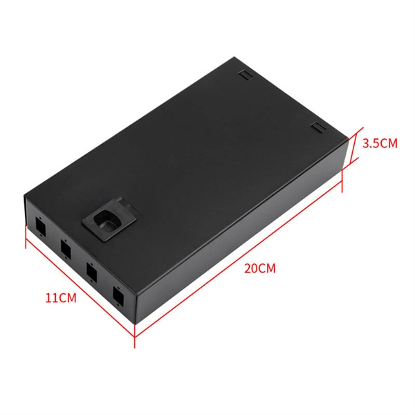
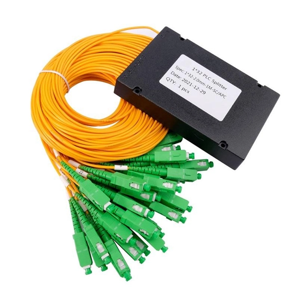
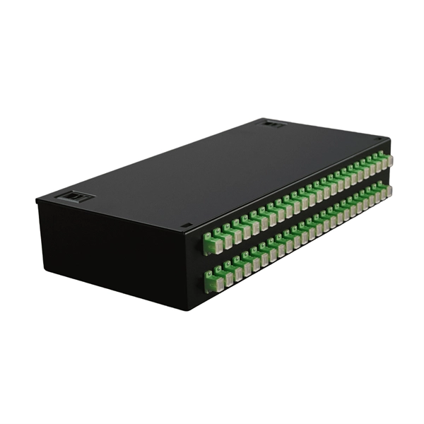
6 core Fiber Optical Splicing With 24 Port LIU || Full Installation || Beginner Watch this video Fiber optic splicing is the process of joining two fiber optic cables together to create a conti. more. Multi-core patch cords are fiber assemblies containing multiple fibers within a single cable jacket, typically available in 4, 6, 12, and 24-fiber configurations. OTRANS strives to provide you with professional, reliable. Corning ® Multicore Fiber (MCF) is engineered for the next generation of AI-driven data centers, delivering up to 4x the optical pathway density within the familiar 125-micron fiber footprint. By integrating four cores into a single strand, MCF enables a step change in bandwidth and simplifies. An optical distribution frame (ODF) is a frame used to provide cable interconnections between communication facilities, which can integrate fibre splicing, fibre termination, fibre optic adapters & connectors and cable connections together in a single unit. It can also work as a protective device. In the complex architecture of fiber optic networks, the Optical Distribution Frame (ODF) serves as the linchpin for organizing, protecting, and distributing optical signals. Whether in data centers, telecom central offices, or enterprise network rooms, ODFs enable efficient fiber management.
[PDF]
All-dielectric self-supporting (ADSS) cable is a type of that is strong enough to support itself between structures without using conductive metal elements. It is used by companies as a communications medium, installed along existing overhead transmission lines and often sharing the same support structures as the electrical conductors. ADSS is an alternative to and with lower installation cost. The cables are designed to be s.
[PDF]