Traditional pluggable optical modules are approaching their physical limits in three core dimensions: power consumption control, signal integrity and port bandwidth density. Low Latency: LPO technology eliminates the need for a DSP, reducing a processing step and thus lowering data transmission latency. This advantage is particularly important in high-performance computing (HPC) scenarios, where minimizing latency is a key factor in achieving optimal performance. By. Among the emerging technologies, LPO (Linear Pluggable Optics), NPO (Near-Packaged Optics), and CPO (Co-Packaged Optics) represent three important stages in the evolution of next-generation data center optical networking. Understanding how these architectures differ is essential for designing. Optical communications are emerging as the next AI computing infrastructure frontier, driven by data interconnection bottlenecks. Lumentum's order book is full through 2028, reflecting surging demand for 800G and 1. 6T optical modules, amplified by Nvidia's strategic investment., May 4, 2026 – GlobalFoundries (Nasdaq: GFS) (GF) today announced the introduction of its SCALE™ optical module solution for co-packaged optics (CPO). GF's SCALE. In Feb. 2023, the State Council issued the "Overall Layout Plan for Digital China Construction. ” It proposes six key tasks,including enhancing the efficient.
[PDF]

An optical module's actual transmit power measured by an optical power meter is lower than the nominal transmit power of the power module. The possible causes are: Bores of the optical module are contaminated. Stable optical power is the foundation of every high-capacity optical transport system. Even minor deviations—whether too high, too low, or unstable—can impact signal integrity, trigger service alarms, or interrupt traffic on DWDM, OTN, or long-haul optical line systems. This is the domain of Cell-to-Module (CTM) power loss, a series of. This paper reviews methods for reducing different optical and electrical loss mechanisms in PV modules and for increasing the optical gains in order to achieve higher CTM ratios. Various solutions for optimizing PV modules by means of simulations and experimental prototypes are recommended. Have you ever experienced an unexpected network outage due to the failure of an SFP/SFP+ optical transceiver? Network outages can bring your ability to communicate and work to a halt, and your IT team will likely be frantically looking for a solution. It is important to understand how to. This article provides an in-depth analysis of two key performance indicators of optical modules: transmitter power and receiver sensitivity. Transmitter power characterizes the average optical power output from the laser under rated conditions, while receiver sensitivity indicates the minimum.
[PDF]
A constant trend in optical modules is to offer higher data rates within the size-limited and thermally-limited form factor by using smaller, integrated Power and Data-Converter solutions. The SFP module is a hot-pluggable optical transceiver used for connecting network switches. It converts electrical signals to optical signals and vice versa. For the 1G SFP module, it is primarily divided into the following two categories: Optical SFP Transceiver Optical transceiver connection RJ45. The optical module serves as a crucial component in optical fiber communication systems, operating at the physical layer, which is the lowest layer in the OSI model. An. Optical modules and media converters are both key photoelectric conversion devices widely used in fiber optic communication, data centers, enterprise networks, and broadband access systems. Many users are confused about their roles, differences, and connection rules. This article will clarify. Microwave photonics technology (MWP), which has been applied to various radar, Telcom, Electronic Warfare systems, is now facing more and more challenging development trend of miniaturization and modular array for increasing node counts and system complexity.
[PDF]

In this tutorial video, we will show you step-by-step how to safely and effectively remove an optocoupler from a circuit board using desoldering wick. We will walk you through the tools you will need, the proper technique for using the desoldering wick, and the precautions to take to av. more In. Whether you're replacing a faulty component, salvaging parts from an old board, or correcting a soldering mistake, knowing how to desolder effectively is essential. This guide will walk you through the tools, techniques, and best practices for desoldering components from a circuit board safely and. Desoldering is a process that removes the solder and components from a printed circuit board or any other type of electronic assembly. This is a meticulous process and it can easily damage the board, or the components, if not properly done. Thus, it is important to know how to desolder properly. If you're desoldering a battery from a circuit board, use flush cutters to cut each wire one-at-a-time to isolate the battery before you desolder the wires. Whenever possible, create an indirect path by soldering connectors onto the battery and the circuit board. This reduces the chance of an. Sorry, an unexpected error has occurred. Why Publish? The Ultimate Guide to Desoldering: From using desoldering irons to sketchily knocking breadboard components off on the side of a table, there are tons of ways to remove components from a circuit board.
[PDF]

Test the GFCI outlet by unplugging the ONT and plugging in a lamp, hairdryer or any corded electrical device you have. Still have no power? You'll need to reset the outlet. Check the two little buttons on the outlet. The following error logs are seen on Gen7 hardware resulting in loss of connectivity. BL-1084 Optical Module reset detected on slot 0 port 1 MCU version 0x19 (0x19) reset-count 51 (50) reset-reason 0x00000000 (0x0000000c). BL-1085. If that does not resolve your internet issue, you can follow these instructions to check the power to, or restart, your ONT. Not sure if you have an ONT? The video below can help you identify if you have one. What is an ONT? Are you a fiber customer? Learn how to identify your Optical Network. The transmit power of the optical module is too low or too high. Check whether an optical module that is certified for Huawei data center switches is installed on the optical interface. The CE series switches must use optical modules. In this article, we will focus on teaching you how to troubleshoot and solve the common three categories of optical module failure. First, the transmission class of the optical module fault investigation and solution method This type of optical module failure mainly includes port not UP, port. Resetting your Optical Network Terminal (ONT) can often resolve connectivity issues. Any FortiGates using optical fiber module. Clean any dust on the fiber patch or patch panel. Plug the SFP back in and assess.
[PDF]

This article compares typical cost ranges across speeds and transceiver types, explains why prices vary, and gives practical guidance for choosing the right optics for a given budget and performance requirement. This article helps network architects and procurement teams run a practical cost analysis for implementing Open RAN using pluggable optical modules across fronthaul and midhaul. All price bands below are market-observed ranges (OEM-branded vs. As per our latest research, the 25G Fronthaul Optical Module market size reached USD 1. 42 billion globally in 2024, demonstrating robust growth driven by the accelerating deployment of 5G wireless networks and expanding data center infrastructure. The market is projected to grow at a CAGR of 18. 7% from 2025 to 2033, reaching a forecasted value of USD 4. 47. The 5G fronthaul optical transceiver modules market is experiencing rapid evolution driven by the global rollout of 5G networks. These modules form the backbone of high-capacity, low-latency communication infrastructure essential for 5G deployment.
[PDF]
This comprehensive guide breaks down the internal structure, core components (TOSA, ROSA, lasers), and operational mechanisms of SFP optical modules, enriched with technical insights and real-world applications. SFP (Small Form-factor Pluggable) optical modules are compact, hot-pluggable transceivers that enable network equipment to connect seamlessly to fiber and copper links. As a leading provider of optical communication solutions, Weunion integrates these. One vital element in the data communication sector is the Small Form-factor Pluggable (SFP) module. In this blog, we will explore the inner workings of these modules, with a particular focus on three essential optical components: TOSA, ROSA, and BOSA. SFP modules are small, hot-swappable devices. Optical modules are devices used to connect network devices, transmit and receive data between network devices, and can be used to convert optical and electrical signals. The optical module is a very important component in an optical communication system. Think of it as the “translator” for your network equipment, converting electrical signals into optical signals. available with a variety of types of copper SFP and fiber SFPs, SFP+. This transceiver module is compliant wi h the small form-factor pluggable (SFP) multi-source agreement (MSA). They industrial performance with an extended operating temperature range. Through real-time monitoring, the DDM.
[PDF]

First, inspect the optical module appearance for physical damage, cracks, missing components, poor solder joints, or burn marks. Next, compare voltage, resistance, and waveform parameters between a normal it and the suspected faulty one, both in powered and unpowered states. As core components of optical communication systems, the proper installation and use of optical modules directly impacts network stability. This article systematically identifies common anomalies during optical module installation. However, during installation and daily operation, various issues may arise. The following will introduce the causes of various problems and how to deal with them. Optical module method/step 1. During the test, the value of the module I BiasADC is 0, and the TXLOP-ADC and. These compact devices convert electrical signals to optical signals and vice versa, enabling data transmission over fiber optic cables. While generally reliable, failures do occur, leading to frustrating downtime, performance degradation, and costly troubleshooting. This comprehensive guide details. Have you ever dealt with sudden network drops from faulty optical modules? Issues like this cannot only break communications, but they can really jeopardize business continuity.
[PDF]
Instantly reprogram, test, and unlock universal compatibility for every optical module — with full diagnostics and OTA updates built in. It lets you check the health of any SFP or QSFP module and program them effortlessly in seconds. We're cutting prices across the entire Ubiquiti SFP lineup — up. SFPTotal devices are full-compatible with official software SFPTotal Wizard which provides a convenient interface that allows to read, decode, edit and write changes to the memory of optical transceivers GBIC, SFP, SFP+, SFP28, XFP, QSFP+, QSFP28 and QSFP-DD form factors. Copy or write optical module profiles instantly. MFT (Mellanox/NVIDIA Firmware Tools) is a set of firmware management utilities for querying firmware details, performing firmware upgrades, and other configuration tasks. It includes four main components: mst, mlxburn, flint, and Debug Utilities. For full specifications, refer to the official. Reprogram and Diagnose Optical Modules Instantly with SFP Wizard The Ubiquiti UACC-SFP-Wizard is a portable, all-in-one optical module programmer and diagnostic tool designed for IT.
[PDF]
Fiber optic connectors in SFP modules are the physical interfaces that connect the transceiver to fiber patch cables, enabling optical signal transmission between network devices. Fiber optic connectors are silently the hero that make fiber networks to have secure, low loss, and easy maintaining connections. In their absence, it would be the only possible approach, splicing that is, which, indeed, is costly and time consuming besides irreversible. These connectors play a. A fiber optic connector is a mechanical device used to align and join optical fibers, enabling light to pass through with minimal loss. This allows for quickly connecting and disconnecting of fiber optic cables without splicing.
[PDF]
This video will show you how to wire a Painless Performance headlight relay into your OBS Chevy / GMC truck or Tahoe to keep the low beams on when you run the high beam lights for much better light coverage in night driving conditions. more. If your headlights suddenly seem too high, too low, or uneven, you likely need to adjust the beam pattern on your headlights. In many cases, poor headlight aim comes from extra weight in the rear of the vehicle. For example, a loaded trunk, hunting gear, tools, or a trailer can push the back end. When we want to replace and upgrade our car headlights, we will pay attention to their brightness and beam pattern. But there is one important factor that is often overlooked - the cutoff line. You can. A blown out low beam bulb can make it difficult to see at night and driving with your high beams on all the time can make it difficult for other drivers to see. Fortunately, fixing a bad low beam is a straight forward process in the majority of vehicles that can be done by most people without just. This DIY will explain how to hookup your DRL's to stay on with your low beams WITHOUT running a switch in the cab. One 30 amp max fuse holder 5. Length of assorted color 14-16 guage wire 6. Female connectors (blue) 7. The right pattern illuminates potential hazards, complies with legal standards, and ultimately keeps you safe. more Audio tracks for some languages were automatically.
[PDF]
It involves encapsulating the optical chip in a metal box filled with inert gas (usually helium) to protect the optical elements from external environmental influences and enhance heat dissipation. COB, BOX, and TO-CAN packaging each offer unique advantages tailored to specific applications. COB packaging integrates components directly onto a PCB, enabling miniaturization and cost efficiency. BOX packaging seals optical chips in a metal enclosure with inert gas, ensuring long-term stability. The COB process refers to a technology that directly mounts bare chips onto a printed circuit board (PCB), connects them via gold wire bonding, and then encapsulates and protects the chips and wires using organic adhesive. Compared with conventional processes, the COB process offers high packaging. Box, COB, and TO can are currently the most prevalent packaging forms for optical components. Box packaging, also known as hermetic sealing, has a long history. Common optical device packaging methods include COB (chip-on-board packaging), BOX and coaxial packaging. What is COB technology? COB (Chip on board) is a form of packaging that directly bonds the. The invention provides an SFP28 SR optical module structure of a COB process, and belongs to the field of optical module structures. The micro-optical module comprises a shell, an unlocking mechanism, an EMI shielding structure, a circuit board, a micro-optical module arranged at one end of the.
[PDF]

These general purpose fiber clamps provide easy means for incorporating glass or plastic optical fibers into optomechanical post assemblies or SM1-threaded components. The precision V-groove and rubber pad are designed to clamp onto the buffer of single mode or multimode fibers without damaging. Harwin supplies a range of surface-mount shield can clips to provide a straight-forward, easy-to-use board-level shielding solution. The combination of SMT clips with a shield can provides a simple and cost-effective method of shielding vulnerable or EMI-radiating board components. Harwin's shield. Check each product page for other buying options. 2-piece kit Fiber optical thermal stripper M8 & fiber optical cleaning clip compatible with bare fiber/bundle and ribbon fiber for 1-48 core dual heating mode and 8-level temperature regulation. Need help?. FPH Fiber Chucks and Holders are designed to terminate bare optical fibers and provide precise coupling and mounting within optical systems. Compatible strain relief boots and fiber clamps are also available. Clamps are larger than clips and designed to hold multiple cables and wires together. Blind plugs are used to close. 1-800-363-1992 Have any questions? Talk with us directly using LiveChat.
[PDF]

When the optical switch module's switching interfaces are all busy or an optical signal needs signal regeneration through an OEO conversion process, the electronic module is used. In modern optical transport networks, optical cross‑connect (OXC) devices are essential for high-speed, flexible signal routing. An OXC switches optical signals between fiber inputs and outputs without converting them to electrical signals, enabling true all-optical routing. In the 1980s, when transmission speeds supported by optical fibers increased from 45 Mbit/s to 2. In essence, an OXC uses photonic switching fabric to route wavelength channels from any incoming fiber to any outgoing fiber. OXC (optical cross-connect) is an evolved version of ROADM (Reconfigurable Optical Add-Drop Multiplexer). As the core switching unit of the optical network, the scalability and economic efficiency of the optical cross-connect (OXC) not only determine the flexibility of the network topology, but. Vendors such as LINK-PP provide comprehensive transceiver and interconnect solutions that ensure OCS architectures perform at their highest potential. This article explores OCS fundamentals, its benefits, use cases, and how LINK-PP optical module solutions complement these networks. Compared with traditional ROADM based on separate boards and inter-board fiber patch cords, OXC uses integrated interconnections to build an all-optical switching resource pool, achieving highly integrated, fiber.
[PDF]
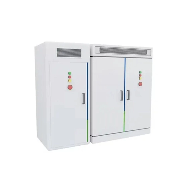
Huijue, a leading BESS manufacturer, offers top-performing lithium battery-powered storage solutions. Ideal for grids, commercial, and industrial applications, our systems seamlessly integrate and optimize renewable energy sources. Huijue Group's energy storage solutions (30 kWh to 30 MWh) cover cost management, backup power, and microgrids. To cope with the problem of no or difficult grid access for base stations, and in line with the policy trend of energy saving and emission reduction, Huijue Group has launched an. Founded in 2002, Huijue Group is a high-tech service provider integrating intelligent energy storage equipment and computer intelligent network communication system integration and application. Huijue Network's products are exported to Europe, North America, Southeast Asia and other countries and. Shanghai, China 5 years 523 staff Main categories: Home energy storage system, Telecom power supply, Energy Storage Batte. Huijue Group was established in 2002 and is a comprehensive high-tech group that integrates diversified development such as communications, the Internet of Things, and new energy. Huijue, a pioneer in Battery Energy Storage Site technology, stands. Since its establishment in 2002, Shanghai HuiJue Technologies Group Co. With its innovative technologies in the fields of intelligent network communication equipment and energy storage.
[PDF]