Run the display device command to check the switch model. Log in to com/onlinetoolsweb/lpcmmt/en/index. html to view the optical module types supported by the switch. If you know the model or type of an optical module, you can view the section "Pluggable Modules for Interfaces" in the Hardware Description to look up parameters of the optical module, including the center wavelength, transmission distance, fiber types supported, receive optical power, and transmit. Taking the Huawei 5700 series switches as an example, the commands to view optical module information are as follows: Transceiver Type :1000_BASE_SX_SFP Connector Type :LC Wavelength(nm) :850 Transfer Distance(m) :300(50um),150(62. 5um) Digital Diagnostic Monitoring :YES Vendor Name. The following uses the Moduletek SFP-10G-LR module connected to a Huawei S6700 switch as an example to introduce how to read information of the connected optical module on a Huawei switch. Run the display transceiver [interface interface-type interface-number | slot slot-id] , to view the information on. Here are the common commands to use to display hardware-related information on Huawei Routers. The inventory information such as serial number, product code,optical module,device, power,voltage,temperature,fan, CPU and memory are very important on operation and troubleshooting purposes. The specific viewing information is as follows:.
[PDF]

An Optical Splitter, also known as a beam splitter, is a passive optical device that divides a single input optical signal into two or more output signals. Conversely, it can also combine multiple signals into one. Knowing the difference between a splitter and an optical coupler helps you build better networks. You make your network work better when you pick the right device for each job. You can connect many users to one port with 1:n or 2:n splitters. By dividing a single optical signal from a central Optical Line Terminal (OLT) into multiple outputs for Optical Network Terminals (ONTs) at users' homes, splitters eliminate the need for dedicated fibers to each residence—slashing infrastructure costs while scaling network reach. This guide. In a Passive Optical Network (PON), a single optical fiber carries massive amounts of data using light. Signal Input: The fiber splitter receives the optical signal from the upstream network node and enters the splitter through the input fiber. Signal Distribution: Inside the splitter, according to the design structure and different. Splitters are passive optical devices that divide or combine optical signals, and they come in various types, including power splitters, uneven splitters, and wavelength-division multiplexing (WDM) splitters. Each type serves specific applications, enabling efficient use of optical infrastructure.
[PDF]

First, inspect the optical module appearance for physical damage, cracks, missing components, poor solder joints, or burn marks. Next, compare voltage, resistance, and waveform parameters between a normal it and the suspected faulty one, both in powered and unpowered states. As core components of optical communication systems, the proper installation and use of optical modules directly impacts network stability. This article systematically identifies common anomalies during optical module installation. However, during installation and daily operation, various issues may arise. The following will introduce the causes of various problems and how to deal with them. Optical module method/step 1. During the test, the value of the module I BiasADC is 0, and the TXLOP-ADC and. These compact devices convert electrical signals to optical signals and vice versa, enabling data transmission over fiber optic cables. While generally reliable, failures do occur, leading to frustrating downtime, performance degradation, and costly troubleshooting. This comprehensive guide details. Have you ever dealt with sudden network drops from faulty optical modules? Issues like this cannot only break communications, but they can really jeopardize business continuity.
[PDF]
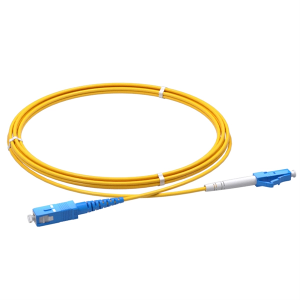
It is designed to transmit data in one direction only. The single-mode optical fiber is designed and engineered to carry one single light mode in a minimal core diameter. It is specified as the best for especially long-distance applications than multimode fiber. Higher-order modes like LP 11, LP 20 etc. Modes are the possible solutions of the Helmholtz equation for waves, which is obtained by combining. Simplex fibers are most commonly used in applications that only require data transmission in one direction. Digital data readouts, interstate sensor relays, and automatic speed and boundary sensors (for sports applications) are all important uses for simplex fiber optic cables. It is designed to. Simplex single-mode fiber is typically used in scenarios where data only needs to be sent in one direction, such as in sensor application like a fire alarm system that sends signals from detectors to a control panel might use simplex fiber. Duplex single-mode fiber is commonly used everywhere else. Single fiber modules (BiDi) use one fiber for both transmitting and receiving data. This saves space and money. Dual fiber modules use two fibers.
[PDF]
We supply 1X9 Single Mode Fiber Optical Transceiver and 1X9 Multi mode Fiber Optical Transceiver, RoHS compliant fiber optic transceiver modules. 1x9 optical transceiver modules are state-of-the-art components designed expressly for the building of high-speed bi-directional communication links that require data rates of up to 1. The modules operate at special extended voltage and temperature (-10 to 85 C) ranges. 1x9 optical. North America Fiber Optics (NAFO) is the sole distributor of Coretek Opto, a leading fiber optic transceiver and optical component manufacturer based in Taiwan. Coretek offers a comprehensive portfolio of high-quality optical products ranging from legacy optical modules to next-generation. 1x9 transceivers are the earliest and oldest-style optical modules. Initially created in the 1990s, they aimed at 100M/1G Ethernet, Fibre Channel, ATM, FDDI, SDH/SONET, and video applications. Then, they were gradually replaced by more advanced and intelligent GBICs, SFPs, SFP+, and QSFPs. 9-pin DIP transceivers for very-legacy switches built before the SFF/SFP standards. Replaces discontinued Methode / Stratos / Optech parts. The original optical module form factor (mid-1990s). It is usually directly cured on the circuit board of the communication equipment and used as a fixed optical module. The 1X9 optical transceiver module can be divided. You are here: Home >> Product >> Optical Transce. >> 1X9 Transceiver.
[PDF]

When the optical switch module's switching interfaces are all busy or an optical signal needs signal regeneration through an OEO conversion process, the electronic module is used. In modern optical transport networks, optical cross‑connect (OXC) devices are essential for high-speed, flexible signal routing. An OXC switches optical signals between fiber inputs and outputs without converting them to electrical signals, enabling true all-optical routing. In the 1980s, when transmission speeds supported by optical fibers increased from 45 Mbit/s to 2. In essence, an OXC uses photonic switching fabric to route wavelength channels from any incoming fiber to any outgoing fiber. OXC (optical cross-connect) is an evolved version of ROADM (Reconfigurable Optical Add-Drop Multiplexer). As the core switching unit of the optical network, the scalability and economic efficiency of the optical cross-connect (OXC) not only determine the flexibility of the network topology, but. Vendors such as LINK-PP provide comprehensive transceiver and interconnect solutions that ensure OCS architectures perform at their highest potential. This article explores OCS fundamentals, its benefits, use cases, and how LINK-PP optical module solutions complement these networks. Compared with traditional ROADM based on separate boards and inter-board fiber patch cords, OXC uses integrated interconnections to build an all-optical switching resource pool, achieving highly integrated, fiber.
[PDF]

The LS-SM3101-20C SFP transceivers are high performance, cost effective modules supporting data rate of 125Mbps/155Mbps and 20km transmission distance with SMF. The transceiver consists of three sections: a Cooled EML laser transmitter, a APD photodiode integrated with a trans-impedance preamplifier (TIA). The AFCT-5745NPZ/UPZ Lead-free Singlemode Optical Transceivers have been qualified in accordance to the requirement of Telcordia Document GR-468-CORE under the supervision of Avago Technologies Quality & Reliabil-ity Department. This report summarizes the qualification tests over a range of. Copyright © 2022 GOC-UZ. See our terms of use and privacy policy. Volza's Solution gives you 100x return in Six Months! Use strategic filters to explore Optical transceiver module Import data like a seasoned analyst, uncovering hidden opportunities in the Optical transceiver module import business. Our database includes 321 Import shipments, involving 63 Buyers. Up to now, MEISU has developed various high-temperature resistant optical devices not only with regular SM fiber, but also with PM fiber array by applying special high-temperature coating to the normal PM fiber, providing muiltiple choices for silicon photonic (SiPh) solder reflowable assembly at.
[PDF]
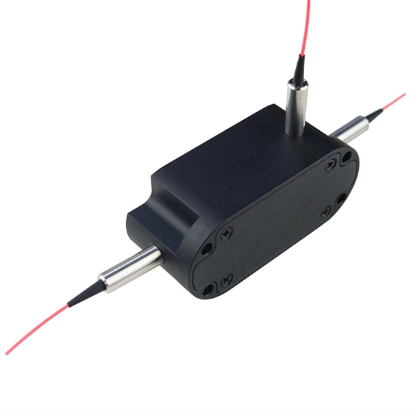
2X2 Fiber Optical Switch connects optical channels by redirecting an incoming optical signal into a selected output fiber. The 2X2 Opto-Mechanical Optical Switches consists of 2 input and 2 output fiber ports that selectively transmits, redirects, or blocks optical power in a fiber. An all-optical Ethernet switch is a network switch whose service ports are entirely optical, meaning every interface uses fiber rather than copper. This design enables end-to-end optical signal transmission, avoiding the conversion between electrical and optical signals at the switch port level. There are no specific requirements for this document. This document is not restricted to specific software and hardware versions. The information in this document was created from the devices in a. The optical ports on the switch are usually paired together, with one TX sender and one RX receiver. The. This gigabit fiber switch has 8-port 1000Mpbs SFP socket and 2ports RJ45 port. The electrical interface will Auto-Negotiate to a 10/100Mbps, or 1000Mbps Ethernet rate without any adjustments. Built on Huawei's unified software platform and equipped with high-performance fully programmable chips, they deliver abundant features including Service Roam.
[PDF]

Test the GFCI outlet by unplugging the ONT and plugging in a lamp, hairdryer or any corded electrical device you have. Still have no power? You'll need to reset the outlet. Check the two little buttons on the outlet. The following error logs are seen on Gen7 hardware resulting in loss of connectivity. BL-1084 Optical Module reset detected on slot 0 port 1 MCU version 0x19 (0x19) reset-count 51 (50) reset-reason 0x00000000 (0x0000000c). BL-1085. If that does not resolve your internet issue, you can follow these instructions to check the power to, or restart, your ONT. Not sure if you have an ONT? The video below can help you identify if you have one. What is an ONT? Are you a fiber customer? Learn how to identify your Optical Network. The transmit power of the optical module is too low or too high. Check whether an optical module that is certified for Huawei data center switches is installed on the optical interface. The CE series switches must use optical modules. In this article, we will focus on teaching you how to troubleshoot and solve the common three categories of optical module failure. First, the transmission class of the optical module fault investigation and solution method This type of optical module failure mainly includes port not UP, port. Resetting your Optical Network Terminal (ONT) can often resolve connectivity issues. Any FortiGates using optical fiber module. Clean any dust on the fiber patch or patch panel. Plug the SFP back in and assess.
[PDF]

This article compares typical cost ranges across speeds and transceiver types, explains why prices vary, and gives practical guidance for choosing the right optics for a given budget and performance requirement. This article helps network architects and procurement teams run a practical cost analysis for implementing Open RAN using pluggable optical modules across fronthaul and midhaul. All price bands below are market-observed ranges (OEM-branded vs. As per our latest research, the 25G Fronthaul Optical Module market size reached USD 1. 42 billion globally in 2024, demonstrating robust growth driven by the accelerating deployment of 5G wireless networks and expanding data center infrastructure. The market is projected to grow at a CAGR of 18. 7% from 2025 to 2033, reaching a forecasted value of USD 4. 47. The 5G fronthaul optical transceiver modules market is experiencing rapid evolution driven by the global rollout of 5G networks. These modules form the backbone of high-capacity, low-latency communication infrastructure essential for 5G deployment.
[PDF]

This guide provides a clear, step-by-step explanation of how to install an SFP module correctly, based on real-world deployment practices. The fastest way to do so is by unplugging the power plug from the power outlet. This is a Class A product. In a domestic environment, this product might cause radio interference in which case the user might be required to take adequate measures Electric shock hazard. This equipment is to be. This Quick Guide covers the model: CCR2004-16G-2S+PC. You can find the product model name on the case label (ID). Or scan the QR code with your mobile phone. lv/um The most important. The Installation of the equipment must comply with local and national electrical codes. Please read the mounting instructions carefully before beginning installation. Failure to use the correct hardware or to follow the correct procedures. The CCR2004 is a high-performance multicore router with twelve 10G SFP+ ports and two 25G SFP28 ports. Before you work on any equipment, be aware of the hazards involved with electrical circuitry, and be familiar with standard practices for preventing accidents. It covers critical preparation checks, proper insertion techniques, hot-swap and safety considerations, common installation mistakes, and practical. The Cisco 8000 series routers support both ZR and ZR+ modules. The Cisco 8200 Series uses a single Cisco Silicon One ASIC to deliver full routing functionality. These fixed port, high-density routers provide 10.
[PDF]

Optical switches will accept inputs nearly immediately as compared to mechanical switches, which could experience a few milliseconds of debouncing lag. Since optical switches do not depend on physical contact, input latency (latency) is severely minimized. This discrepancy can just be a couple of. An optical transistor, also known as photonic transistor, optical switch or light valve, is a device that switches or amplifies optical signals. Any communication protocol (Ethernet, ATM, etc. Significant. High Speed: Optical switches provide a high-speed data transmission capacity that surpasses that of traditional electrical switches. Interference Resistance: They are immune to electromagnetic interference, ensuring a reliable data transfer. Low Power Consumption: With no need for O-E-O conversion. Optical switching is the process of controlling the destination of individual optical information signals. This technology allows for high bit rate transmission to be switched between various optical lines. The core component enabling optical switching is the Optical Switch. Figure: Optical Switch. Serving as the backbone of high-speed fiber-optic networks, data centers, and emerging technologies like quantum communication, optical switches enable efficient light signal management with a small latency. As global demand for bandwidth surges due to 5G, AI, and cloud computing, advancements in.
[PDF]

An optical module's actual transmit power measured by an optical power meter is lower than the nominal transmit power of the power module. The possible causes are: Bores of the optical module are contaminated. Stable optical power is the foundation of every high-capacity optical transport system. Even minor deviations—whether too high, too low, or unstable—can impact signal integrity, trigger service alarms, or interrupt traffic on DWDM, OTN, or long-haul optical line systems. This is the domain of Cell-to-Module (CTM) power loss, a series of. This paper reviews methods for reducing different optical and electrical loss mechanisms in PV modules and for increasing the optical gains in order to achieve higher CTM ratios. Various solutions for optimizing PV modules by means of simulations and experimental prototypes are recommended. Have you ever experienced an unexpected network outage due to the failure of an SFP/SFP+ optical transceiver? Network outages can bring your ability to communicate and work to a halt, and your IT team will likely be frantically looking for a solution. It is important to understand how to. This article provides an in-depth analysis of two key performance indicators of optical modules: transmitter power and receiver sensitivity. Transmitter power characterizes the average optical power output from the laser under rated conditions, while receiver sensitivity indicates the minimum.
[PDF]
Read the topics and perform the procedures in this order: 1. Preparing for Installation 2. Planning a Switch Data Stack 3. Installing and Removing an SFP and SFP+ Module 6. Where To. The following information is for FCC compliance of Class A devices: This equipment has been tested and found to comply with the limits for a Class A digital device, pursuant to part 15 of the FCC rules. These limits are designed to provide reasonable protection against harmful interference when the. What Can I Do If a Message Is Displayed Indicating that an Optical Module Is Not Supported During Stack Port Configuration? - S300, S500, S2700, S5700, and S6700 V200R023C00 Configuration Guide - Device Management - Huawei How Do I Install a License File for a Stack System? How Do I Specify a. Page 1 Catalyst 3650 Switch Hardware Installation Guide April 2016 Cisco Systems, Inc. com Cisco has more than 200 offices worldwide. Addresses, phone numbers, and fax numbers are listed on the Cisco website at www. Text Part Number: OL-29734-01. Page 2 OR ITS. This guide describes the hardware features of the Catalyst 3650 switches. It describes the physical and performance characteristics of each switch, explains how to install a switch, and provides troubleshooting information. This guide does not describe system messages that you might receive or how.
[PDF]

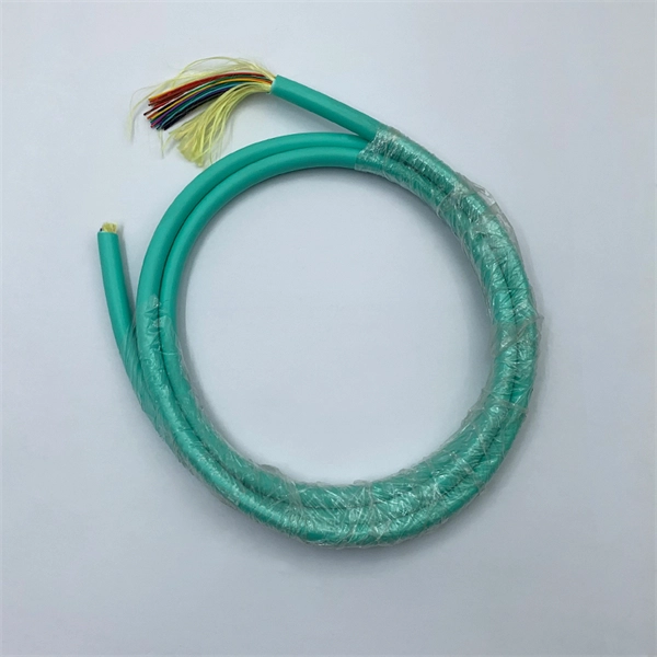
One of the core advantages of MPO patch cords is their high-density integration. Traditional patch cords have only 1-2 cores per cord, while MPO patch cords can integrate 12-48 cores, enabling multi-port connections with a single cord. Fiber cores are the heart of fiber optic cables, transmitting light signals that carry data. Made from either high-quality glass or plastic, the core plays a critical role in determining the cable's performance. The total number of cores for a 1pc fiber patch cable is calculated as the number of. Multi-core patch cords are fiber assemblies containing multiple fibers within a single cable jacket, typically available in 4, 6, 12, and 24-fiber configurations. The outer sheath is clearly marked with core count indicators. MTP/MPO cables are a class of high-density multi-core fiber optic connectivity solutions widely used in data centers and telecom networks, which are designed to achieve fast connection of multi-core fiber optics through a single interface. In the context of accelerating digitalization, the rational. The 16-core MPO patch cord, a high-density optical fiber connector, has become an ideal choice for 400G networks and beyond due to its superior optical performance, flexible compatibility, and efficient cabling capabilities. This report analyzes the key technical parameters, primary application.
[PDF]