The optical module is usually composed of Transmitter Optical Subassembly (TOSA, containing a laser LD Chip), Receiver Optical Subassembly (ROSA, containing a photodetector PD Chip), a driving circuit, and an optical and electrical interface. Its schematic is shown in. This section explains the structure of a typical pigtail butterfly module, which gets its name from the two rows of seven leads at right angles on each side of the metal package plus an optical fiber pigtail at one end (Fig. Let's look at the internal structure (Fig. 2) of a common butterfly. Optical modules are devices used to connect network devices, transmit and receive data between network devices, and can be used to convert optical and electrical signals. The optical module is a very important component in an optical communication system. Optical devices are the core components of optical modules. TOSA and ROSA in Common Optical Transceiver Modules For ordinary optical transceiver modules, there are two optical devices, TOSA and ROSA, which have opposite effects.
[PDF]

Run the display transceiver [ interface interface-type interface-number | slot slot-id ] [ verbose ] command to view information about the optical module on a specified interface. In optical communication equipment, an optical module (Optical Module) contains several types of semiconductor chips that work together to complete the transmission and processing of optical signals. These chips typically include laser chips, photodetector chips, driver chips, transimpedance. When the optical module on an interface is faulty, you can run the display commands to view information about the optical module. Today, we will deeply analyze the four mainstream models of 100G QSFP28 dual-fiber optical modules: QSFP28-100G-SR4, QSFP28-100G-LR4, QSFP28-100G-ER4 and. The following uses the Moduletek SFP-10G-LR module connected to a Huawei S6700 switch as an example to introduce how to read information of the connected optical module on a Huawei switch. Figure 1 Schematic Diagram of Optical Module Connected to Switch 1. Optical Module Status Check Run the. Upgrade to 100G or 400G optics and save. Cisco Transceiver Modules - Learn product details such as features and benefits, as well as hardware and software specifications. Network administrators have a major challenge determining the right Cisco SFP modules, understanding complex model numbers that directly affect network performance and stability.
[PDF]
Segmented dimming is a feature of the Magic Leap 2 that applies a darkening tint behind specific digital content. Similar to a drop-shadow, this dimming improves the visual quality of a digital object by making it appear brighter or more opaque. The dimmer uses a lower resolution panel and therefore, developers must be conscious of it's use and is best used for larger objects. As of the February 2023 release, all virtual. The main scene of this project displays two cubes, one cyan and one red. The Segmented Dimmer material opacity will adjust based on the MLCamera stream value calculations. Think of this as a tint applied to the background under all the virtual content, in which you can control its opacity value. A Segmented Dimmer, which allows applications to locally. Th is function is commonly referred to as dimming control. Th is article describes some basic LED theory and several techniques used to provide dimming control to switched-mode LED drivers. Th e concept of the brightness of visible light from an LED is fairly easy to understand. Assigning a. It the utility model is related to LED light source room lighting field, more particularly to a kind of segmented LED dimming control circuit, a kind of segmented LED dimming control circuit, the light-source brightness of LED lamp is automatically adjusted to realize by the collective effect of.
[PDF]

Wavelength: 1310nm, 1550nm, or CWDM/DWDM wavelengths. LR (Long Range): 10km, 1310nm, Blue latch. Each SFP module operates at a specific wavelength, and to avoid confusion, manufacturers use color-coded pull rings for easy identification. Here's a quick guide: 🔹 850nm (Black) – Short-distance multimode fiber (up to 550m) 🔹 1310nm (Blue) – Longer reach, typically used for single-mode fiber (up. Wavelength division multiplexing modules differ from other optical modules in center wavelengths. Wavelength division. Coarse Wavelength Division Multiplexing (CWDM) SFP modules are a practical and cost-effective solution for expanding network capacity while keeping equipment simple and scalable. Selecting the right wavelength for CWDM SFPs is essential to ensure optimal performance, minimal interference, and. Every optical transceiver operates at a specific wavelength, typically measured in nanometers (nm). Their pull. SFP (Small Form-factor Pluggable) is a compact, hot-swappable module used in network devices such as switches, routers, and servers to provide network connectivity and is widely used in network communications. Think of it as the “translator” for your network equipment, converting electrical signals into optical signals.
[PDF]

Optical Modules Market Segments - by Product Type (Transceivers, Receivers, Transmitters, Amplifiers, and Others), Application (Data Centers, Telecommunication, Enterprise Networking, and Others), Distribution Channel (Online Stores, Direct Sales, Indirect Sales . Optical Modules Market Segments - by Product Type (Transceivers, Receivers, Transmitters, Amplifiers, and Others), Application (Data Centers, Telecommunication, Enterprise Networking, and Others), Distribution Channel (Online Stores, Direct Sales, Indirect Sales . Data centers will keep dominating optical module demand as AI and cloud drive revenue growth through 2030. Optical module demand is being pulled in two directions at once, faster bandwidth for dense networks and tighter constraints on power, security, and lead times. 8% during the forecast period 2025-2031. The potential shifts in the 2025 U. tariff framework pose substantial volatility. The Optical Module Market size was estimated at USD 26. 53 billion in 2025 and expected to reach USD 30. The accelerating explosion of global data traffic has thrust optical modules into the heart of modern communications.
[PDF]
The main trade show for the large optical module industry is the Optical Fiber Conference (OFC), that is held annually in southern California. Other prominent shows for the industry include ECOC in Europe and FOE in Japan.
[PDF]
Connectorized attenuators often have a quite compact housing, essentially looking like a fiber-optic adapter. Some of these devices provide a fixed level of attenuation, quantified as the insertion loss in decibels. An optical attenuator, or fiber optic attenuator, is a device used to reduce the power level of an optical signal, either in free space or in an optical fiber. The basic types of optical attenuators are fixed, step-wise variable, and continuously variable. Optical attenuators are commonly used in. Fiber-optic attenuators are a specific type of optical attenuators which are used in fiber optics, e. for achieving a suitable signal level for a data receiver in a telecom system. It primarily ensures the power or amplitude of a signal is lowered without significantly distorting its waveform. The attenuator circuit will allow a known source of power to be reduced by a predetermined factor, which is usually expressed as decibels.
[PDF]

Average Optical Power: How bright the light is (measured in dBm). Too dim? Your signal gets lost in the fiber. Extinction Ratio: The difference between “on” (1) and “off” (0) light power. A higher ratio = cleaner signals. Transmitter Side: An electrical signal hits a laser diode (LD) or LED, which spits out light. Receiver Side: Light enters a photodetector (like a tiny solar cell), which turns it back into electricity. A built-in amplifier boosts the signal for your. The average transmitted optical power refers to the optical power output by the light source at the transmitting end of the optical module under normal working conditions, which can be understood as the intensity of light. In communication, we usually use dBm to represent optical power. However, in practical use, we adopt the average Tx power. The transmission power is related to the. This article provides an in-depth analysis of two key performance indicators of optical modules: transmitter power and receiver sensitivity. Transmitter power characterizes the average optical power output from the laser under rated conditions, while receiver sensitivity indicates the minimum. An optical module is a connecting module that serves as an optical-electrical conversion device. At the receiver end, the optical signals are reconverted into electrical.
[PDF]

Learn how to monitor SFP optical power on Cisco switches, interpret Tx/Rx levels, and troubleshoot fiber link issues. Step-by-step CLI commands, model-specific guidance, and best practices included. In this article, we will break down the key factors influencing TX/RX power, explain how to calculate the optical power budget, and provide actionable insights for optimizing your network's performance using SFP modules. SFP (Small Form-Factor Pluggable) modules are compact transceivers that allow. SFP (Small Form-factor Pluggable) optical modules are compact, hot-pluggable transceivers that enable network equipment to connect seamlessly to fiber and copper links. Even if an interface appears up, degraded Tx/Rx levels can cause intermittent flapping, packet loss, or err-disabled states. Think of it as the “translator” for your network equipment, converting electrical signals into optical signals. The most two important factors of the SFP transceiver: Output power (TX power) and receiver sensitivity (RX sensitivity). The optical TX power is the signal level leaving from that device, which should be within the transmitter power range. The RX sensitivity is the incoming signal level being. In current network communication, SFP optical modules are an indispensable physical foundation for building network channels. They form high-speed channels for optical signal transmission. Therefore, to ensure their.
[PDF]
Run the display device command to check the switch model. Log in to com/onlinetoolsweb/lpcmmt/en/index. html to view the optical module types supported by the switch. If you know the model or type of an optical module, you can view the section "Pluggable Modules for Interfaces" in the Hardware Description to look up parameters of the optical module, including the center wavelength, transmission distance, fiber types supported, receive optical power, and transmit. Taking the Huawei 5700 series switches as an example, the commands to view optical module information are as follows: Transceiver Type :1000_BASE_SX_SFP Connector Type :LC Wavelength(nm) :850 Transfer Distance(m) :300(50um),150(62. 5um) Digital Diagnostic Monitoring :YES Vendor Name. The following uses the Moduletek SFP-10G-LR module connected to a Huawei S6700 switch as an example to introduce how to read information of the connected optical module on a Huawei switch. Run the display transceiver [interface interface-type interface-number | slot slot-id] , to view the information on. Here are the common commands to use to display hardware-related information on Huawei Routers. The inventory information such as serial number, product code,optical module,device, power,voltage,temperature,fan, CPU and memory are very important on operation and troubleshooting purposes. The specific viewing information is as follows:.
[PDF]
Remove the module from the receiver frame. Use the Allen wrench to remove the module cap screws located at the top, middle and bottom of the module (Figure B). For 37 and 16/16 position use a Phillips screw driver to remove the (2) 2-56 screws. Terminating fiber optic cables essentially means putting connectors on fiber optic cable so that you can connect the cable to various devices or network components. Think of it as the equivalent of connecting the dots in a complex puzzle; without proper termination, the whole system can break down. How to remove/disconnect fibre cable from Telus modem? Pull the green thing from the metal thing If you pull it out make sure to put the fiber connection in a plastic bag or blow it with air before plugging it back in, Fiber laser modules and a single spec of dust/lint/crumb can affect your speeds. Terminating fiber optic cable is a crucial step in the installation process, as it ensures a reliable and efficient connection. The contact can only be installed from one side. Ensure that the contact is squared up with the corresponding module location. Once in place, pull the wire. The transceivers for the router are hot-removable and hot-insertable field-replaceable units (FRUs). After you remove a transceiver or when you change the media-type configuration, wait for 6. IN THIS VIDEO I WILL SHOW YOU How to Disconnect Optical Fiber Cables from the Connector #DISCONNECTOPTICALFIBER.
[PDF]
The single-fiber optical module has only one optical fiber port, and only one optical fiber can be inserted to transmit and receive optical signals at the same time. One fiber is required for. Single fiber modules (BiDi) use one fiber for both transmitting and receiving data. This saves space and money. Dual fiber modules use two fibers. They are easier to set up and give steady communication. It uses WDM technology to realize the bidirectional transmission of optical signals on one optical fiber. BIDI module only has 1 port, wave filtering through the filter of module, and finished the transmitting of 1310nm optical signal. Appearance and use: single fiber optical module has one optical fiber interface, which connects one optical fiber; dual-fiber optical module has two optical fiber interfaces, which connect two optical fibers; 2.
[PDF]
If you encounter any of these issues, check the optical connector for damage or dirt, inspect the fiber optic patch cord, ensure the optical module is correctly installed, and check the device settings for compatibility. Subsequently, the driver semiconductor laser (LD) or light-emitting diode (LED) emits modulated optical signals at the corresponding rate. After transmission through the optical fiber, the receiving interface converts the optical signals into electrical signals using a photodetector diode and. An optical module is a typically hot-pluggable optical transceiver used in high-bandwidth data communications applications. Optical modules typically have an electrical interface on the side that connects to the inside of the system and an optical interface on the side that connects to the outside. The Transmitter Optical Sub Assembly (TOSA) is responsible for the emission of light. Its primary function entails converting electrical signals into optical signals.
[PDF]
GIGALIGHT 800G QSFP-DD SR8 is a hot-pluggable optical transceiver module designed for 800G SR8 Ethernet links in data centers. It adopts 100G PAM4 and VCSEL technology and can realize 800G data exchange within 100m. 800G OSFP/QSFP-DD | Transceiver Modules - FS FS United StatesFREE SHIPPING on Orders Over US$79 Contact Us United States / $ USD All Products Solutions Services Resources Contact Us FREE SHIPPING on Orders Over US$79 United States Home Optical Transceivers Ethernet/RoCE Networking 800G. Cisco QSFP-DD and OSFP 800G ZR/ZR+ digital coherent optics modules enable 800G traffic over amplified Dense Wavelength-Division Multiplexing (DWDM) links up to 120 km for 800ZR and over 1000 km for 800G ZR+. Cisco ® QSFP-DD and OSFP 800G ZR/ZR+ coherent optics modules enable 800G traffic over. Your request has been submitted successfully. Our sales manager will contact you soon. High-density 800G OSFP and QSFP-DD transceivers support InfiniBand and RoCE, enabling 100m to 2km transmission via MMF and SMF. Have any questions? Talk with us directly using LiveChat. It is compatible with most switches(CISCO, Juniper, Arista,Brocade,H3C,HPE, DELL, etc) OSFP 800G SR8 is an Eight-Channel, Parallel, Pluggable, Fiber-Optic OSFP for 800Gigabit.
[PDF]
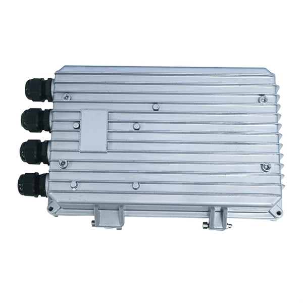
As core components of optical communication systems, the proper installation and use of optical modules directly impacts network stability. The customer has 2 alarms on BTS3900 (GSM-R network). BBU Optical Module Transmit/Receive Fault 2. RF Unit Maintenance Link Failure The results of this alarms was restarting of the RF unit. After combining the RRU log analysis and the alarm of the optical module, the radio frequency maintenance. An alarm is generated when the transmit or receive power of an optical module is out of the allowed range. Indicates the MIB object ID of the alarm. Indicates the parent. After ruling out traditional problems like passive intermodulation (PIM), poorly aimed antennas and/or other coaxial problems, dirty fiber connectors account for 60 to 75% of the alarms, failures, and poor throughput problems found in modern cellular systems today. It has been several years since. All or part of the products, services and features described in this document may not be within the purchase scope or the usage scope. About This Document Introduction This document describes the routine hardware maintenance of the BBU3900. This article systematically identifies common anomalies during optical module installation. Combining hardware principles with practical experience, it.
[PDF]