
Optical transmission windows are specific wavelength ranges where light travels through fiber with minimal attenuation (signal loss) and dispersion (distortion). These low-loss windows are essential for maintaining the performance and reach of fiber optic communication systems. Fiber optic cable is a type of cabling that contains one or more optical fibers for transmitting data at high speeds and/or over long distances using light. These fibers are most commonly made of glass and are very thin, typically less than a tenth of the width of a human hair. Fiber optic cable. This is your "QuickStart" guide to testing fiber optic cable plants, patchcords and communications equipment with a fiber optic light source and power meter. We'll give you the basic information you need and provide some printable references. Optical power, required for measuring source power, receiver power and, when used with a test source, loss or attenuation, is the most. Fiber optic loss testing is an essential part of maintaining reliable, high-performance fiber optic networks because it helps identify potential issues and ensures that the system meets the required performance specifications. In this blog, we'll explore what a power meter and light source are and. This part of IEC 61280 is applicable to the measurement of attenuation of installed optical fibre cabling plant using multimode optical fibre.
[PDF]

BER is calculated by comparing the transmitted sequence of bits to the received bits and then counting the number of errors. Whether you're a network engineer validating new inventory or an integrator preparing for deployment, knowing how to test optical transceiver modules can save time, reduce failures, and ensure SLA compliance. Unchecked optical modules can cause: Testing ensures compliance with IEEE 802. 3 and MSA. Bit Error Rate (BER) is a measure of telecommunication signal integrity based on the quantity or percentage of transmitted bits that are received incorrectly. Essentially, the more incorrect bits, the greater the impact on signal quality. It is defined as the ratio of the number of bits received in error to the total number of bits transmitted. It quantifies the error frequency caused by disturbances like statistical noise. What causes bit errors in optical data transmission? In optical systems, bit errors are. One of the most important ways to determine the quality of a digital transmission system is to measure its Bit Error Ratio (BER). Through the interpretation of actual test reports, it.
[PDF]

Numerical relay are embedded with specialized digital signal processor (DSP) as the computational hardware. By using DSP as the relay's processor, the relay is capable of meeting the fundamental protective requirements such as reliability, sensitivity, selectivity and speed . Thus, various protective devices are used to protect the power system, of which digital signal processor (DSP) numerical relays are capable of significantly improve protection operations. Therefore. Manuals and User Guides for Samwha DSP DSP-VIP-PM Motor Protection. We have 1 Samwha DSP DSP-VIP-PM Motor Protection manual available for free PDF download: Manual Samwha dsp DSP-VIP-PM Motor Protection Pdf User Manuals. View online or download Samwha dsp DSP-VIP-PM Motor Protection Manual. Many of the new protection relays are microprocessor based and are generally referred to as numerical relays. This means that signals from transducers are sampled at fixed time intervals, digitally encoded, and processed by equipment which resembles a computer to derive relaying information, e.
[PDF]
Ceramic ferrules and sleeves are often used in optical connectors, attenuators, fiber stubs, and other optoelectronics requiring low signal loss. They are designed to align and protect the fragile fiber ends while ensuring low insertion loss and high return loss. Kyocera's extrusion molding process creates ferrules with excellent coaxiality, and our precision machining ensures excellent concentricity with precise. Fiber optic connectors are indispensable passive devices in fiber optic communication systems. Most fiber optic connectors consist of three parts: two mating plugs (ferrules) and a coupling sleeve. The two ferrules are installed into the tail ends of the two optical fibers; the coupling sleeve. While some industrial applications use ceramic ferrules for high-temperature stud welding, the primary, high-technology market is focused on fiber optics. This guide provides a definitive look at these high-precision components. Its main function is to fix the optical fiber and ensure the stability and accuracy of the optical fiber connector. The production process of ceramic ferrules includes powder. Their manufacturing uses a series of advanced process technologies, including nano-zirconia powder injection molding material formulation and forming technology, slender micro-hole forming technology with an inner hole diameter of 0. 125mm and a length of 12-15mm, precision ceramic processing.
[PDF]
Connectorized attenuators often have a quite compact housing, essentially looking like a fiber-optic adapter. Some of these devices provide a fixed level of attenuation, quantified as the insertion loss in decibels. An optical attenuator, or fiber optic attenuator, is a device used to reduce the power level of an optical signal, either in free space or in an optical fiber. The basic types of optical attenuators are fixed, step-wise variable, and continuously variable. Optical attenuators are commonly used in. Fiber-optic attenuators are a specific type of optical attenuators which are used in fiber optics, e. for achieving a suitable signal level for a data receiver in a telecom system. It primarily ensures the power or amplitude of a signal is lowered without significantly distorting its waveform. The attenuator circuit will allow a known source of power to be reduced by a predetermined factor, which is usually expressed as decibels.
[PDF]
Fiber optic cables have revolutionized the way we transmit data, offering greatly improved speed and reliability compared to traditional copper cables. These cables use light to carry information, resulting in faster and more efficient communication. A TOSLINK optical fiber cable with a clear jacket. A fiber-optic cable, also known as an optical-fiber cable, is an assembly similar to an electrical cable but containing one or more optical fibers that are used to carry. What is DSL internet? Obsolete in most populated areas, DSL delivers internet using traditional telephone lines. It's different from the old-school dial-up of yesteryear, as you can use the internet and your landline at the same time, but it's still one of the older technologies out there. The process relies on a principle called Total Internal Reflection. What is Fiber Optic Cable? A Fiber Optic Cable is used to transmit data through fibers (threads) or plastic (glass). This pack of glass which is within sorts of threads transmits modulated messages along sunshine waves. There are many advantages of using these cables over other kinds of. Fiber-optic cables on cable drums are versatile. They are used wherever a glass fiber connection is temporarily required. For any kind of events, e. Trade fairs, sports events, conferences, filmed productions, etc. High-Speed Transmission: Fiber optics use light.
[PDF]
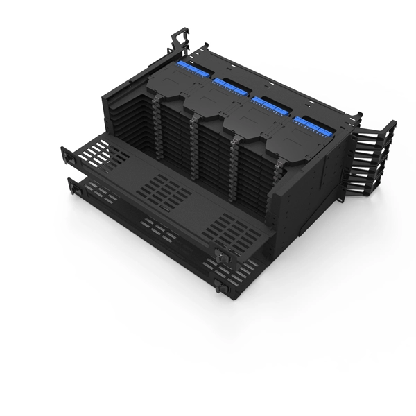
A well-chosen patch panel not only organises your fibre connections but also provides protection and flexibility for future expansions. In this comprehensive guide, we'll explore the key factors to consider when selecting the perfect patch panel for your network infrastructure. Choosing the right fiber optic patch panel is one of the most important decisions you'll make when building or upgrading a fiber network. While patch. Whether you're planning to upgrade your home internet connection or just curious about how fiber technology works, understanding the essential fiber optic equipment is the first step. From the optical network terminal to the router that brings your home online, each piece plays a critical role in. Structured wiring begins with a structured networking panel. These panels have ports for input cables and output cables. The right structured wiring can deliver top performance from your electronics. The panels accept cable from outside providers to distribute the signals to each room of your home. If you already know what your project requires, check out our complete Fiber Patch Panel selection. What is a Fiber Patch Panel? Fiber optic patch. Fiber optic installation is the way to go! It's super reliable and perfect for streaming, gaming, or using multiple devices. This guide breaks down the process in easy steps so you know what to expect. Aerial Service Drop: A cable coming from a pole to your house, connected at a small box called an.
[PDF]
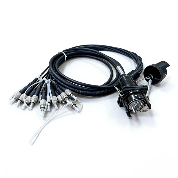
Mass fusion splicing can fuse up to all 12 fibers in one ribbon at once. Entire ribbons can be spliced simultaneously. Standard mass-fusion color-coded pigtail kits contain a. Traditional Fusion Splice-On Connectors with pigtails provide factory-polished performance with field-termination convenience within harsh environments. com offers Less-Than-A-Truckload “LTL” option for products that cannot be shipped via parcel shipping. For products that will be shipped via LTL, you will be provided with a set of Accessorials to select from to provide Anixter with additional shipping considerations, such as. The Relevance Inspector will open in the Coveo Administration Console. SDX Pigtail Fusion Metal Splice Module pre-loaded with duplex LC adapters (Blue) and 12-fiber OS2 LC/UPC individual pigtails. Works with all SDX Enclosures. SDX 12- and 24-fiber splice modules protect and organize heat shrink fusion spliced fibers (up to 12 or 24 fibers) inside a fiber enclosure. The modular design enables faster field splicing and simple management of pigtails within the housing. The M4 Splice Cassette is designed for use with Single-Mode OS2 fiber, houses 12 fibers, and provides LC UPC Duplex ports.
[PDF]
Cable laying services install fiber optic cable or copper cable in buildings and office complexes, or over large distances. They are staffed by cable technicians who perform cable preparation, jointing, termination, testing, commissioning, maintenance, and troubleshooting tasks. Installing fiber optic cables underground involves far more than digging trenches and placing cables. It forms a critical backbone for modern communication networks across both urban and rural environments. Project success depends on careful planning, precise installation practices, and proper. Installing underground fiber optic cables is critical to establishing high speed internet infrastructure that delivers reliable connectivity for businesses nationwide. Unlike traditional copper systems, fiber optic cables require specialized handling techniques and precise installation methods to. These skilled professionals ensure that your home or business is equipped with the latest fiber optic technology, providing blazing-fast Internet speeds and robust connections. This guide walks you through the entire process of fiber cable installation, from the initial assessment to the final. This involves burying or installing fiber-optic cables along predetermined routes. During this phase, locators identify existing utilities to prevent damage.
[PDF]

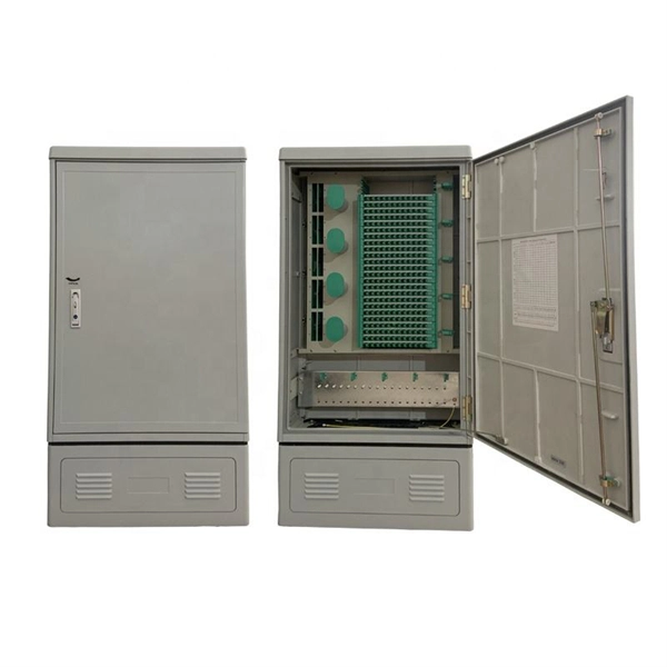
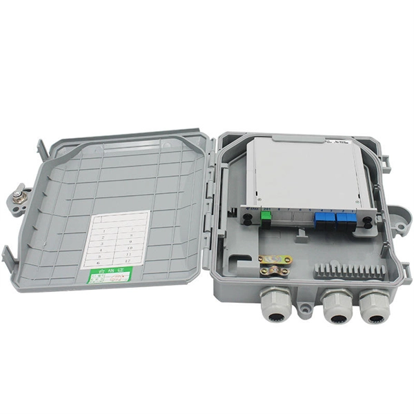
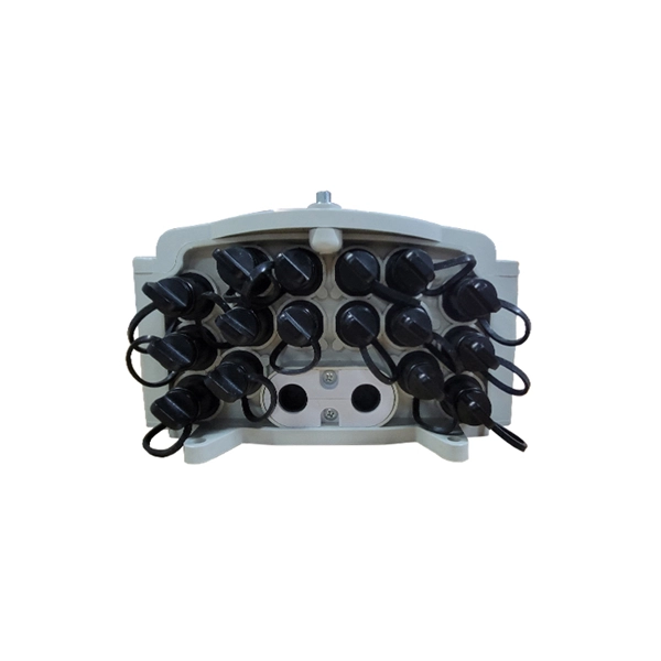
A typical fiber optic splice enclosure consists of several key components that work together to protect and organize the fiber splices. Standard enclosures contain: 1) Housing, 2) Cable fixation clamps, 3) Splice trays, 4) Sealing system. A splice box (also known as splice distributor) is a housing in which fiber optic cables begin or end. Fiber optics are fanned out in splice boxes that are situated at the end of fiber optic transmission paths. Optical cable joint box The optical cable joint box permanently connects two optical cables together and has a joint part for protecting components. The optical cable connection part, that is, the optical cable joint, is the part where the. An optical cable split fiber box, also known as a fiber distribution box or fiber optic splice closure, is a device used to terminate, splice, and distribute optical fibers. In this response, we will focus on the. This guide optimizes the original text by delving deeper into the three pillars of fiber network longevity: the impact of splicing technology, the strategic selection of splice boxes, and the essential maintenance protocols needed to ensure sustained, high-speed functionality. Fibre optic cables are manufactured in standardized lengths –.
[PDF]
A fiber-optic sensor is a sensor that uses optical fiber either as the sensing element ("intrinsic sensors"), or as a means of relaying signals from a remote sensor to the electronics that process the signals ("extrinsic sensors"). Fibers have many uses in remote sensing. Depending on the application, fiber may be used because of its small size, or because no electrical power is needed at th. Intrinsic sensorsOptical fibers can be used as sensors to measure, , and other quantities by modifying a fiber so that the quantity to be measured modulates the,,, or transit time. Extrinsic fiber-optic sensors use an, normally a one, to transmit light from either a non-fiber optical sensor, or an electronic sensor connected to an optical transmitter. A major benefit of e. It is well-known the propagation of light in optical fiber is confined in the core of the fiber based on the total internal reflection (TIR) principle and near-zero propagation loss within the cladding, which is very important f.
[PDF]
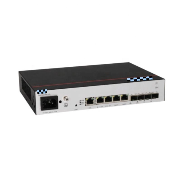
The term 10G optical module generally refers to hot-pluggable transceivers in SFP+ form factor that support 10 Gigabit Ethernet (10GbE) transmission. A typical 10G SFP+ transceiver integrates a laser transmitter, a photodiode receiver, and a control IC within a compact housing. 10GBASE-LR is a 10-gigabit Ethernet optical standard that operates at 1310 nm over single-mode fiber (SMF), supporting link distances of up to 10 km. It is typically implemented using SFP+ transceivers and defined under IEEE 802. 10G-LR module has become one of the most widely. What is SFP? SFP refers to the small form pluggable factor. In actuality, it is a form of 10 Ethernet Transceiver that enables both: With these features, you can manage high data speed. The SFP works with small form factors (SFF) connectors that ensure high data speeds and physical compactness. So. As enterprises migrate to high-bandwidth environments, 10G optical modules remain one of the most widely adopted solutions for data centres, enterprise backbones, and metropolitan networks. However, facing the numerous models on the market, such as LRM, SR, LR, ER, ZR and other optical modules, how to choose the most suitable. High-speed data transmission in enterprise and data center networks is driven by 10G optical modules. Choosing the proper SFP+ module, whether it be SR, LR, or ER, can have significant impacts on performance, reliability, and costs.
[PDF]
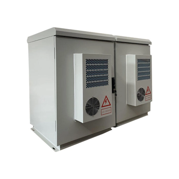
Wide temperature range technology enables devices to operate reliably in extreme temperatures, from freezing to high heat. It is essential for outdoor, military, and industrial environments. Temperature switches are essential devices used to monitor and control temperature in industrial and mobile equipment. They automatically open or close an electrical circuit when a preset temperature is reached, helping protect systems from overheating or unsafe operating conditions. Unlike transmitters that continuously send analog or digital signals, temperature switches provide a discrete ON/OFF output when the measured. What is a temperature switch? A temperature switch or thermal switch is used to open and close switch contacts. The switching status of the temperature switch changes depending on the input temperature. Basically, the thermal. A switch that is used for opening and closing switch contacts is known as a temperature switch. Generally, these switches are. What does a temperature switch do? What is the principle behind mechanical temperature switches? What are electronic temperature switches? What is the switching hysteresis? What is the difference between a temperature switch and a temperature controller? How do bimetal temperature switches work?. These switches play a vital role in ensuring the safety and control of machinery and equipment operating at high temperatures, preventing overheating and potential hazards.
[PDF]
Fiber optic connectors can be categorized according to different standards such as utilization, fiber count, fiber mode, and transmission method. They are also divided into single-mode and multimode types based on their distinct characteristics. This guide will walk you through the most common fiber connector types, explaining their characteristics, advantages, and typical use cases. Whether you're planning an FTTH deployment, upgrading a data center, or working in telecom infrastructure, this guide will help you make informed decisions. Compared to Copper cables, Fiber connector types are incredibly varied. Where copper twisted pairs tend to terminate with an RJ45 plug, fiber optic connectors come in all sorts of shapes and sizes, with all manner of different use cases in mind. An optical fiber connector is used to join optical. With a wide variety of connector types available, choosing the right connector for your network can be challenging. Learn how each connector works, where it's used, and how to choose the right option for today's high-density, high-speed networks. It is a precise coupling device that joins fiber optic cables quickly, enabling faster connection and disconnection than splicing. The connector mechanically orients the fiber cores, allowing light to pass and travel through. In this guide, you'll explore various types of fiber optic cable connectors, each with unique features and best uses. We'll also provide practical advice.
[PDF]

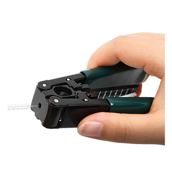
Fusion splicing is the most widely used method of splicing as it provides for the lowest loss and least reflectance, as well as providing the strongest and most reliable joint between two fibers. Virtually all singlemode splices are fusion. There are two main methods of splicing: mechanical splicing and fusion splicing. This blog will delve into the nuances of each method, comparing their costs, labor efficiency, network performance, and more, to help you decide which splicing technique is best suited for your needs. Why splice? Fiber. Fusion splicing is the process of fusing or welding two fibers together usually by an electric arc. Fiber splicing means joining two optical fibers (permanently or temporarily) such that light guided in one fiber and reaching the joint (splice) can be transferred into the second fiber with low insertion loss. Another method of connecting optical fibers is termination or connectorization, which consists of processing the end of a fiber optic bundle so that it can be connected to other fibers or devices through fiber optic. Fiber Optic Cable is a form of modern network cable that has a far greater capacity than electrical communication connections. Splicing is typically required during cable installation, maintenance, or network expansion. The goal is to achieve the lowest possible optical loss (signal.
[PDF]
