There are two main types of RF attenuators: fixed and variable. Fixed Attenuators: Provide a fixed amount of attenuation, typically designed using discrete or chip resistors. These can be further divided into:. Attenuators are designed to change the magnitude of the input signal seen at the input stage, while presenting a constant impedance on all ranges at the attenuator input. A compensated RC attenuator is required to attenuate all frequencies equally. Without this compensation, HF signal measurements. Let's look at the common types of attenuators Fixed attenuators, as their name suggests, are fixed or unchanging. These are used in applications that don't require changing levels of attenuation or where an occasional replacement of one attenuator with another is acceptable. Say we now add a 6 dB pad between. An RF Attenuator is a two-port passive electronic device designed to reduce (attenuate) the power or amplitude of an RF signal. They can adjust the signal strength by controlling the amount of attenuation, ensuring that the signal reaches the desired level for transmission in a.
[PDF]
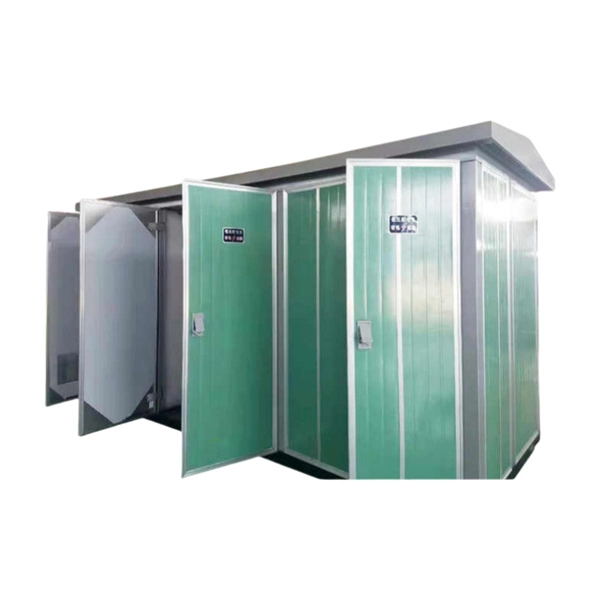
M8 Mild steel fixings should be torqued to 28 NM (20. For reliable busbar connections, component selection matters—but torque control matters more. Best practices include: Yet even with perfect hardware, insufficient torque leads to high resistance. Proper busbar torque specification ensures enough compressive force to stabilize resistance over. Page 1 Medium-Voltage Switchgear Type 8DB10Extendable Fixed-Mounted Circuit-Breaker Switchgear up to 40. 5 kV Double Busbar, Single-pole Metal-Enclosed, Gas-Insulated Medium-Voltage Switchgear INSTALLATION AND OPERATING INSTRUCTIONS Order No. 9 Revision: 06 Issue: 26-02-2016. Failure to follow these instructions can result in injury or equipment damage. The elastic washers placed on the external sides of the connections and busbars help ensure for. At its core, busbar design must meet stringent industry standards, primarily addressing four key areas: thermal performance, mechanical strength, material selection, and electrical integrity. This comprehensive approach ensures that busbars operate stably under rated current conditions and can. Only install switchgear in closed rooms suitable for electrical equipment. Ensure that installation, operation and maintenance are carried out by specialist electricians only. Fully comply with the legally recognized standards (IEC or local), the connection conditions of the local electrical.
[PDF]
There are two main types of optical splitters based on manufacturing techniques: Fused Biconic Taper (FBT) splitter and Planar Lightwave Circuit (PLC) splitter. Optical splitters and couplers split or combine light—distributing signals injected into a single fiber strand to multiple fibers, enabling point to multi-point communication in Fiber To The Home (FTTH) networks based on ITU. T PON standards such as GPON, XGS-PON and new 25 and 50G standards. Optical splitters, also known as fiber optic splitters, are integral components in fiber optic networks, enabling one fiber input to be divided into multiple outputs. This capability is crucial in telecommunications, especially in Passive Optical Networks (PONs), where fiber-optic networks must. FS PLC Fiber Optic Splitters, Bare/Blockless/ABS/LGX Splitter/Rack Mount Types, support 1xN light distribution, with low IL and PDL for high-reliability transmission. Deploying compact FS PLC Splitters to simplify your networks, perfectly fits your PON, EPON, FTTX, etc. Conversely, it can also combine multiple signals into one. Unlike active devices (which require power), splitters operate without electricity, relying solely on the physics of. Fiber optic splitter is a passive optical device used to distribute optical signals, which can divide input optical signals into multiple outputs to meet the fiber optic access needs of multiple terminal devices.
[PDF]
This list includes both standards-based and real-world technical cable types utilized in fiber-optic infrastructure, telecoms, enterprise, and outdoor applications. • OFC: Optical fiber, conductive• OFN: Optical fiber, non-conductive• OFCG: Optical fiber, conductive, general use.
[PDF]
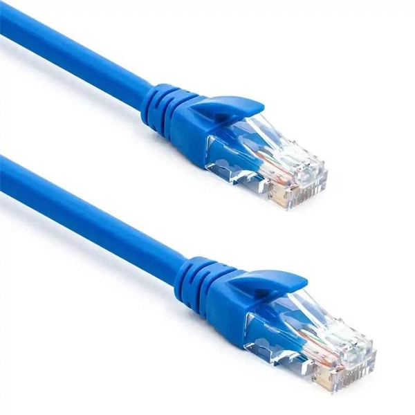
Discover the most common types and models of Direct Attach Cables (DACs), including 10G, 25G, 40G, 100G, 200G, and 400G. A Direct Attach Cable (DAC) is a factory-assembled high-speed copper cable with fixed connector “module-style” ends. It's widely used for short-reach links in data centers because it delivers low latency, simple deployment, and cost-efficient interconnects-especially for rack-level connectivity. These cables come pre-terminated with SFP (Small Form-factor Pluggable) or QSFP (Quad Small Form-factor Pluggable) connectors which simplify network setup. High-speed cable is a kind of low-cost short-distance connection solution to replace optical modules. Both of its ends have cable assemblies of a module, which are connected. Direct attach copper (DAC) cables are twinax copper assemblies with fixed transceiver-like ends. They deliver high bandwidth, low latency, and great density for top-of-rack (ToR), server-to-switch and switch-to-switch connections. This article summarizes the common DAC categories and. What is a Direct Attach Copper (DAC) Cable? Common Types And Uses Summary : Direct Attach Copper (DAC) cables provide fast, reliable, and cost-effective short-distance connections for data centers, enterprise networks, and top-of-rack setups. With passive and active variants, DAC cables offer.
[PDF]

A ladder type cable tray tee is a fitting used to create a branch in a cable tray system, allowing cables to be routed in three directions. Its "T" shape provides a secure and efficient way to split cables from a main tray into two separate paths, ensuring organized and flexible. A cable tray tee and tee cover are components used in cable management systems to support and protect electrical and data cables. Here's a brief explanation of each:. Rigid steel cable tray tee fitting with zero tangent, safety bottom, and full accessory support. ventilation to heat producing cable such as power communication and other with the same or different width of the cable run. All fittings are available in sizes and types corresponding to the straight cable tray sections. These fitting are including: elbow, horizontal cross, vertical inside. NOTE : Equal or un equal tees can be supplied. When ordering state widths W1xW2xW3.. Office: 147/22 Nguyen Sy Sach Street, 15 Ward, Tân Binh Dist, HCMC,VN. Is it possible to connect 2 cabletrays with a "branch piece (left picture)" instead of a "tee (right picture)". The tee has 3 connectors, the branch piece only has 1 connector. I would like to ajust the "Type properties -> Fittings -> Tee" with the branch family, but can't get it accomplished.
[PDF]

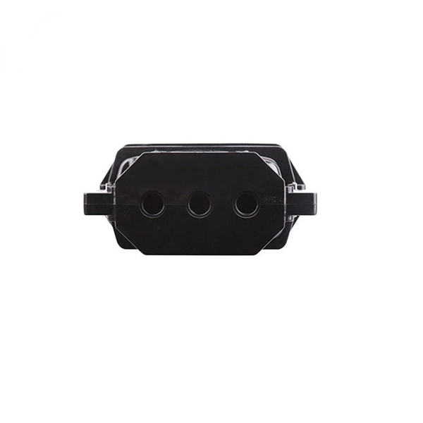
The main components of a splice box are the splice cassette that picks up the fibers and their reserves, and the front panel which contains different connectors for transmitting signals via copper or fiber optic cables. A splice box (also known as splice distributor) is a housing in which fiber optic cables begin or end. Fiber optics are fanned out in splice boxes that are situated at the end of fiber optic transmission paths. It typically consists of two parts: an outer housing and an internal structure. In this response, we will focus on the. The FSB series of indoor wall mount enclosures are designed for centralized splice-only applications. These boxes are well suited as optical cable splice collection points for DAS (Distributed Antenna Systems), MTU (Multi-Tenant Unit) commercial business applications, and MDU (Multi-Dwelling Unit). Fiber optic splice closures permanently connect two fiber optic cables together and have a splice that protects the components. The optical cable connection part, that is, the optical cable joint, is the part that protects the connection between two or more optical cables by the optical cable. Splicing refers to the permanent connection of two optical fibers to form a continuous optical connection.
[PDF]
There are connectors designed for single mode and multimode fiber optic cables, which differ in core size, bandwidth, and optimal use cases as explained in this comprehensive guide to fiber optic cable t.
[PDF]
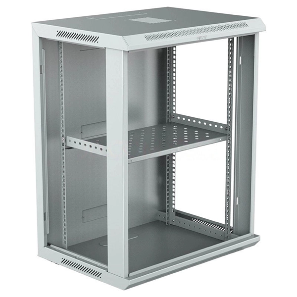
A cable ladder tray system is characterized by its two longitudinal side rails connected by individual rungs, resembling a ladder. This design provides exceptional strength and ventilation, making it ideal for supporting heavy power cables and a large volume of wiring. Explore our full collection of Metallic Ladder 3D Drawings, including horizontal fittings, vertical fittings and metallic tray. Filter Results Results refresh instantly as you filter. Used to identify and differentiate offerings within a particular product line. Ladder tray is the most common and the most economical type of tray, also providing maximum ventilation for cabling. Rungs are fastened to the side. Our cable tray design considerations guide details key factors to consider when designing cable tray systems for industrial and commercial applications. Designed to provide maximum ventilation and ease of cable management, cable ladder trays are ideal for heavy-duty applications where multiple cables need to be organized and. Hubbell's NEXTFRAME® Ladder Tray is the effective and widely used cable runway that supports and delivers bundles of cable between cabinets, racks, and closets, along walls, and suspended from ceilings. The Ladder Tray features light, rugged, tubular steel construction. Think of it as a sophisticated “highway” for cables, keeping them organized, protected, and easily accessible. A complete system is made up of.
[PDF]
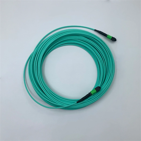
Choosing the right fiber type, typically single-mode, enhances the performance of 1310nm modules, allowing for longer transmission distances. 1310nm lasers support various data rates, from 1Gbps to 100Gbps, providing flexibility for different network needs. In fiber-optic communication, a single-mode optical fiber, also known as fundamental- or mono-mode, is an optical fiber designed to carry only a single mode of light - the transverse mode. When selecting a module, consider factors. Single-mode fibers (also called monomode fibers) are optical fibers which are designed such that they support only a single propagation mode (LP 01) per polarization direction for a given wavelength. Higher-order modes like LP 11, LP 20 etc. then do not exist — only cladding modes, which are not. Gigabit single-mode fiber optic module Common parameters of optical modules 1. Center wavelength 1) 850nm (MM, multi-mode, low cost, but short transmission distance, usually only 500M); 2) 1310nm (SM, single mode, large loss during transmission, small dispersion, generally used for transmission. Single mode fiber (SMF) is a type of fiber optic cable that only allows one light mode to transmit at a time. Generally, single mode cable has a narrow core diameter of 8 to 10µm (micrometers), which can propagate at the wavelength of 1310nm and 1550nm. They feature low attenuation benchmarks 2 and minimal dispersion. They use OS1 or OS2 OS1 or OS2 classifications to.
[PDF]
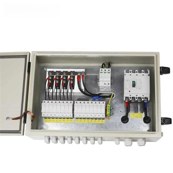
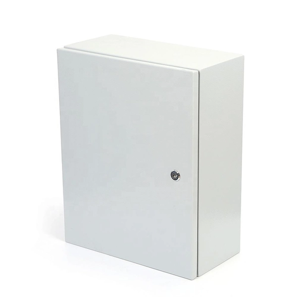
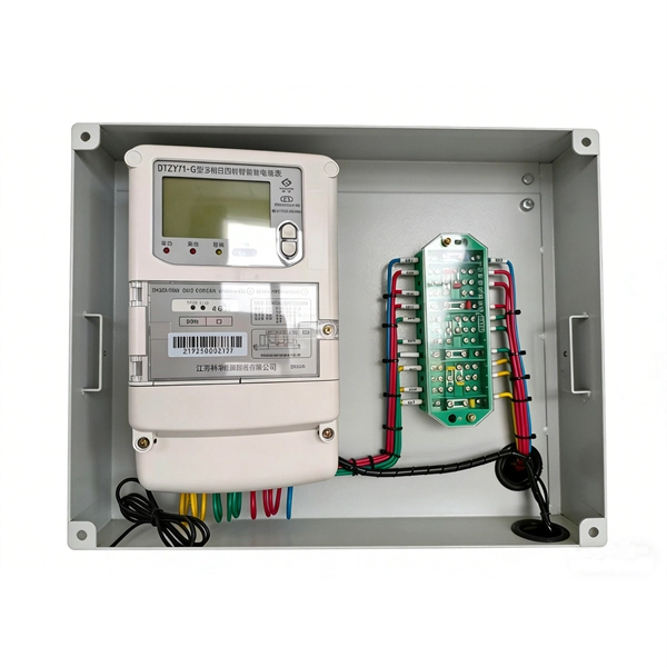
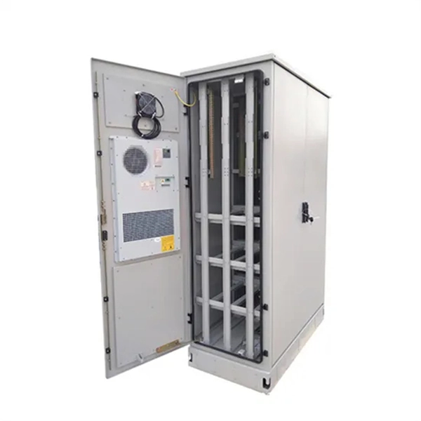
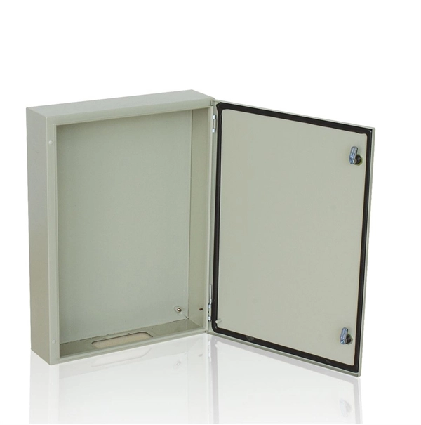
A power distribution box (also called PDU or distro) directs electricity from a main source to multiple circuits. It acts like a hub or traffic controller, managing power flow to different areas or devices. Our Christy range of concrete enclosures, lids and accessories provides robust, durable utility access in deliberate traffic environments and high-impact applications. With its AASHTO HS20 load rating, Christy enclosures are optimized for use on roadways that experience heavy vehicular traffic. A power distribution box is a key part of any electrical system. Without it, managing power would be messy, unsafe, and inefficient. In this guide, we'll explain what a power. The distribution box (DB box) helps safely and efficiently distribute electrical power. Today, electrical systems are essential for homes and industries. To learn more about distribution boxes and how they work, keep reading. It helps organize, protect, and control electrical connections in residential, commercial, and industrial electrical systems. Distribution. Electrical systems power our homes, offices, and industrial facilities, but behind every reliable electrical setup lies a crucial component that often goes unnoticed: the distribution box. This essential piece of equipment serves as the nerve center of your electrical system, managing power flow.
[PDF]

Cable Trays* — Max two 24 in. (610 mm) wide by max 6 in. (151 mm) deep open-ladder cable tray with channel-shaped side rails formed of 0. 54 mm) thick aluminum or min 0. In practice, cable tray dimensions are a system of interrelated measurements —width, depth, length, and material thickness—that directly affect cable fill compliance, heat dissipation, structural loading, and long-term expandability. From an engineering standpoint, cable tray dimensions are not. Perforated Cable Tray System expertly constructed from high-grade stainless steel, offering exceptional durability and resistance to corrosion. With side height 100mm. A properly designed and installed cable tray system will provide. Studs — Wall framing to consist of wood studs or channel shaped steel studs. Wood studs to consist of nom 2 by 4 in. Additional studs shall be used to completely frame. Best Size: Here, deep trays (75mm to 150mm) are used since power cables are typically thick and heavy. Data cables, such as your Wi-Fi or computer ones, are extremely sensitive. They do not get hot; however, they do not like to hang or sag. In case a data cable folds in an excessive manner, the. ect the minimum bend ra-dius for cables as they exit the bottom of the cable tray. A rung spacing of 6 to 9 inches (150 to 230 mm) is preferable when the cable tray cont d for instrumentation and control applications that require additional protec eferred to support and protect numerous small.
[PDF]

The main group of impedance relays is distance protection devices. loss of synchronism protection, loss of excitation protection, or impedance automatics like fault locator. Impedance Relay Definition: An impedance relay, also known as a distance relay, is defined as a device that triggers based on the electrical impedance measured from a fault's location to the relay. Working Principle: The operation of an impedance relay hinges on the balance of voltage-induced. When a system has too many radial lines protection using time delay overcurrent relay becomes impractical. This problem can be solved to an extent by using distance relays. Distance relays uses voltage and current to calculate the. Distance relay protection has been defined as a part of relay protection in power systems that detects and isolates faults based on the distance between the relay and fault points. Unlike overcurrent relays, which only respond to the magnitude of current, a distance relay measures the impedance of. Such relays are called Distance Relays or Impedance Relays. In an impedance relay, the torque produced by a current element is opposed by the torque produced by a voltage element. The relay will operate when the ratio V/I is less than a predetermined value. The voltage transformer measures the voltage across the protected equipment, while the current transformer measures the current flowing through it.
[PDF]
There are connectors designed for single mode and multimode fiber optic cables, which differ in core size, bandwidth, and optimal use cases as explained in this comprehensive guide to fiber optic cable.
[PDF]
A spectrometer is a scientific instrument used to separate and measure components of a physical phenomenon. Spectrometer is a broad term often used to describe instruments that measure a continuous variable of a phenomenon where the spectral components are somehow mixed. In a spectrometer can separate white and measure individual narrow bands of color, called a spectrum. A.
[PDF]