This list includes both standards-based and real-world technical cable types utilized in fiber-optic infrastructure, telecoms, enterprise, and outdoor applications. • OFC: Optical fiber, conductive• OFN: Optical fiber, non-conductive• OFCG: Optical fiber, conductive, general use.
[PDF]
The Tuvalu Vaka Cable system contains four fiber pairs that land in Funafuti, the capital of Tuvalu. Tuvalu's first undersea telecommunications cable — the Vaka Cable — is now live, marking a major milestone in the country's digital transformation. The cable will deliver more reliable and affordable internet across Tuvalu, improving digital access and inclusion. The USD 56 million (AUD 80 million). The Tuvalu Vaka Cable is the first international telecommunications cable connecting Tuvalu, being a branch of 688km linking Funafuti, the capital of Tuvalu, with the trunk of the Bulikula cable system, part of Google's Pacific Connect initiative. The new undersea cable will deliver faster. TUVALU celebrated the official activation of its submarine cable, the Tuvalu Vaka Cable, on 24 October 2025. Funded by Australia, the United States, Taiwan, New Zealand and Japan and supported by Google's inclusion of Tuvalu in the Central Pacific Connect system, the activation of the cable is a. Tuvalu Telecommunications Corporation (TTC) announced the successful landing of the nation's first submarine cable, the Tuvalu VAKA Cable, marking a monumental leap forward for connectivity and digital inclusion for Tuvalu.
[PDF]
Metal conductors in cables serve to conduct electricity, while optical cables use optical fibers to transmit light signals, and optical fibers are thin, flexible media that transmit light beams, forming the core part of optical cables. Let's take a closer look at. Yes, there can be differences between optical cables in terms of their construction materials, connector types, and the quality of the glass fibers used. These factors can affect the cable's ability to transmit data effectively over long distances and at high speeds. It's important to choose the. Toslink—short for “Toshiba Link”—is a very specific subset of fiber‑optic technology created in 1983 to move consumer‑level digital audio from one box to another. Let's take a closer look at these differences. Cables physically connect these devices, enabling them to communicate within a network. In computer networking, it is very important to know the distinctions between the different. These cables are used mainly for digital audio connections between devices. A fiber-optic cable, also known as an optical-fiber cable, is an assembly similar to an electrical cable but containing one or more optical fibers that are used to carry light. They are mainly used in telecommunications, data transmission and consumer electronics. Compared to traditional cables that carry electrical signals, optical ones have Cables some advantages.
[PDF]

Find and discover Cable manufacturers and suppliers for all products in Malta, featuring details on their shipment activities, trade volumes, trading partners, and more. View all cable buyers based on products in Malta. Use the full potential of Europe's leading B2B marketplace. Subscribe to global trade data intelligence to discover new business. SM CABLES is a private company duly registered and approved by the local authorities for the Manufacture of Low Voltage Cables and forms part of a group engaged in building construction and electrical trading activities. As a manufacturing base that commenced in 1996, SM CABLES had acquired all the. We supply a range of both indoor and outdoor fibre optic cables that have different construction types, such as tight buffer, loose tube and microcable, to suit different application types be it for direct burial, duct installation, aerial (figure-8 and self-supporting) or blown fibre applications. Network Infrastructure Design, Installations, copper and fibre termination, cable laying, testing and certification. Overhead & Underground Cable Installations and Cable recovery. "At Conversa, our mission is to use our expertise and experience to create an effective and ethical match between the. Who we are, and what we stand for. As a manufacturing base that commenced in 1996, SM (Cables) acquired all the.
[PDF]

Fiber optic loss calculation formula: Total link loss (LL) = Cable attenuation + Connector attenuation + Fusion attenuation [Note: If there are other components (such as attenuators), their attenuation values can be added]. Intrinsic Optical Fiber Losses comprise of absorption loss, dispersion loss and scattering loss caused by the structural defects. The detailed information about these optical losses and how to reduce them are. Calculate fiber optic signal loss based on cable length, attenuation, and connector losses. Determine cable loss, connector loss, and total system loss in decibels (dB) to assess signal quality and repeater requirements. Fiber optic loss is calculated in two parts: cable loss and connector loss. This calculator determines fiber loss based on input power, output power, and the length of the fiber optic cable. In summary, fiber optic loss is. Use this worksheet to input values for all variables that will impact your system's performance. After entering your values, please ensure you click the 'Calculate Link Loss' button at the bottom of the page to generate your total link loss. This step is necessary to see if your system falls within. Optical fiber loss is a term for signal loss affecting transmission reliability. Optical fiber loss is.
[PDF]
Fiber testing is the process of verifying the performance of optical fiber cabling. This process includes a range of tests and measurements such as insertion loss, optical return loss, and fiber length. It encompass.
[PDF]

What is the main cause of attenuation in fiber? Attenuation in fiber mostly happens from absorption and scattering. The fiber material takes in some light as it moves. Both of these things make the signal weaker as it goes through the. Optical Signal Attenuation is the single greatest factor limiting the distance and performance of your network. Understanding it is crucial for anyone involved in data centers, telecommunications, or enterprise networking. This guide will demystify signal loss, explore its causes, and show you how. Optical fibers are a key component in modern communication systems, carrying signals over long distances. However, even the most advanced optical fiber suffers from attenuation, which is the loss of signal power as it travels along the fiber. Understanding the causes of signal loss and implementing mitigation strategies is essential for maintaining network efficiency. From infrastructure planners to telecom engineers. Optical fiber technology enables rapid data transmission over vast distances by guiding light signals through thin strands of glass. Losses can be introduced by various means such as intrinsic material absorption, scattering, bending, connector loss and more.
[PDF]
Fiber optic cables often follow a color-coding system to indicate their type: Single-mode fibers - Typically yellow. Multi-mode fibers (OM1 & OM2) - Usually orange or sometimes gray. Choosing the right type of fiber optic cable is essential for reliable and cost-effective network performance. The two main types — Single Mode (SM) and Multimode (MM) — differ in construction, performance, and application. This guide explains how to identify them by appearance, labeling, and. When figuring out if a fiber cable is single mode, one must know the different classifications. Essentially, fiber optics are mainly categorized as: Single Mode Fiber (SMF): This type features a small core and uses laser technology to send a single light mode. Single mode fibers are used for. Knowing how to tell the difference between single mode and multimode fiber is crucial for network efficiency; the core distinction lies in the fiber's core diameter and how light travels through it, affecting bandwidth, distance, and cost. This allows for a single mode of light to travel through the core. With clear tables and updated details, it serves as a comprehensive reference for technicians handling modern fiber optic installations. We'll cover single mode, multimode, and armored fiber cables below. This small diameter core, typically around 9 microns in diameter, allows only one.
[PDF]
Usually, the 10G/25G grey light optical modules with a short transmission distance are applied for connecting AAU/DU with WDM/OTN/SPN. The connections between WDM/OTN/SPN network devices can be achieved by 10G/25G/50G/100G dual-fiber or single-fiber bidirectional. Compared with Draft A (2013-07-30), this issue includes the following new topic: 2. This section describes engineering specifications of an AAU, including input power and equipment specifications. 7. In 2/3/4G networks, 10Gbps optical modules are generally enough for CPRI interfaces. In 5G networks, CPRI is also upgraded to eCPRI. Currently, 5G of the bearer network mainly uses 25Gbps optical modules. Next, ETU-LINK will introduce the types of optical modules used by 10G SFP+ and 25G SFP28. What is the difference between the 5G bearer network and the traditional optical transmission network? The main difference is that 5G fronthaul needs to support CPRI/eCPRI protocol. Most of the AAU of 5G base stations are deployed outdoors. In order to resist harsh environments such as high. The optical modules used to connect BBU and RRU devices are optical modules and optical fibers. Product Versions The following table lists the product versions related to this document. 25G SFP optical module adopts the wavelength of 850nm, with an operating.
[PDF]
3 specifies performance and transmission requirements for premises optical fiber cable, connectors, connecting hardware, and patch cords. Optical fiber transition methods used to connect cabling from an array connector to simplex or duplex connectors are also. ANSI/TIA-568-C. (FOA) was founded in 1995 to help develop the workforce to build the fiber optic networks to support a rapid expansion in communications and the Internet. The charter of the FOA was to promote professionalism in fiber optics through education, certification, and. ANSI/TIA‑568. 3‑E “Optical Fiber Cabling and Components Standard” was developed by the TIA TR‑42. 11 Optical Fiber Systems Subcommittee and published in September, 2022. A full catalog of TIA specs is at org/ Learning More About Standards and Codes There are a number of ways of finding out more about cabling. This specification covers the general requirements and characteristics for cables utilizing optical fibers for signal transmission. NOTE: The base document is not DLA Land and Maritime managed and is only here as a courtesy. Please use ASSIST Quick Search to ensure you have the latest version. This. This section covers Agency requirements for fiber optic service entrance cables intended for aerial installation either by attachment to a support strand or by an integrated self-supporting arrangement, for underground application by placement in a duct, or for buried installations by trenching.
[PDF]

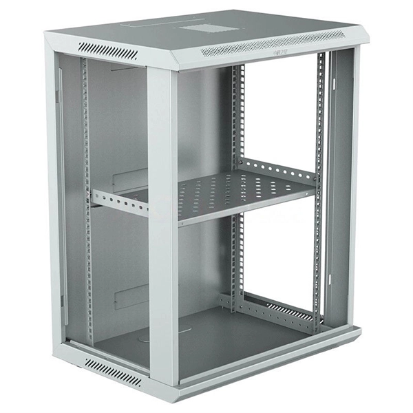
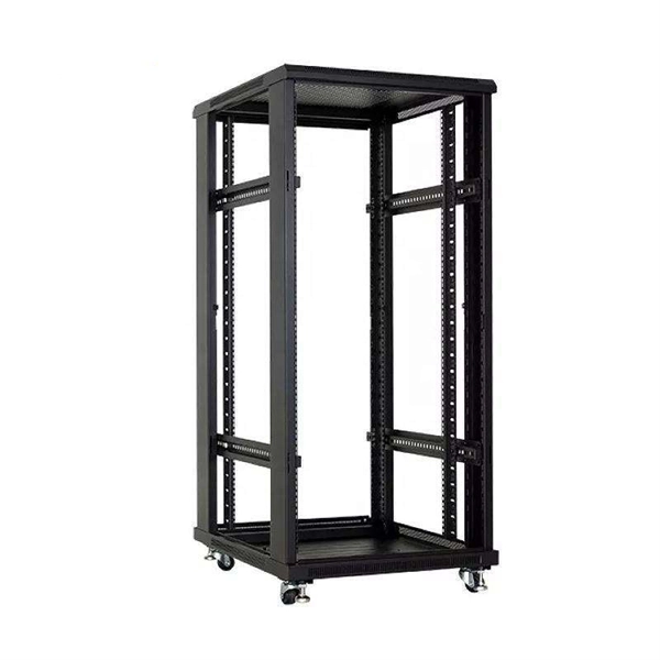
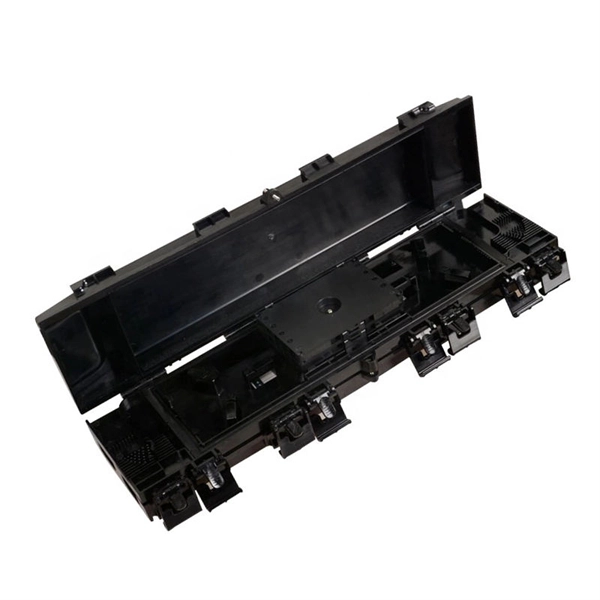
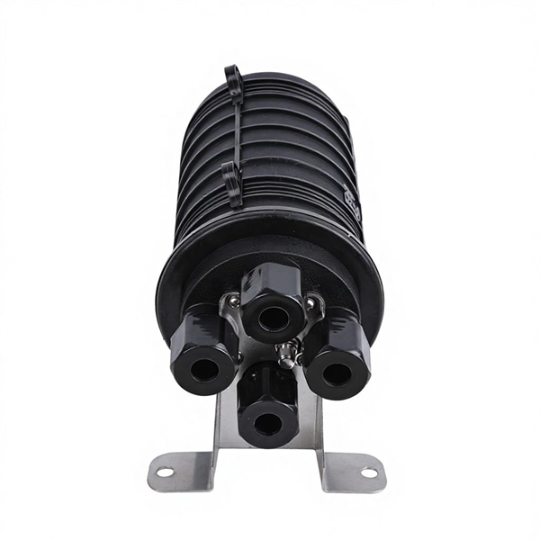
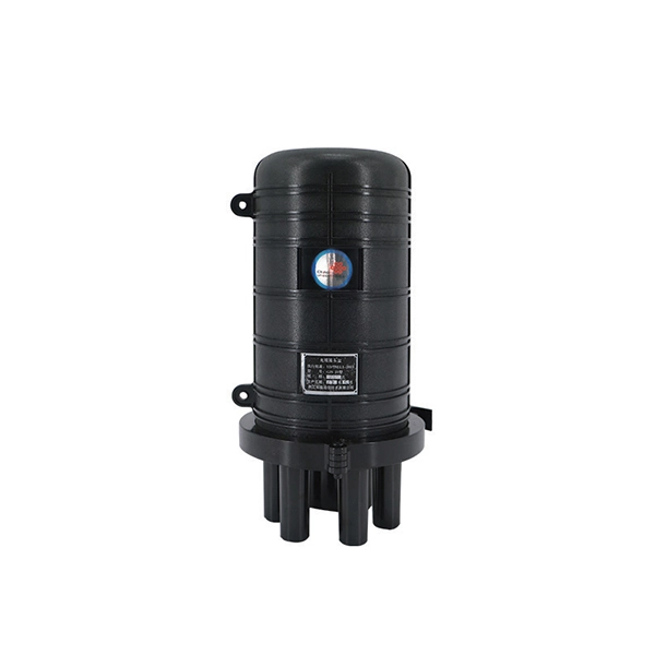
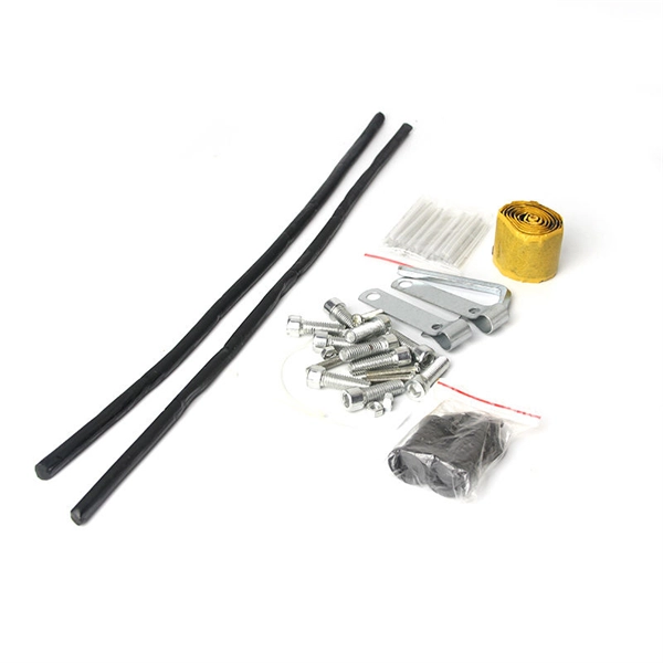
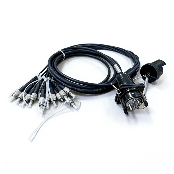
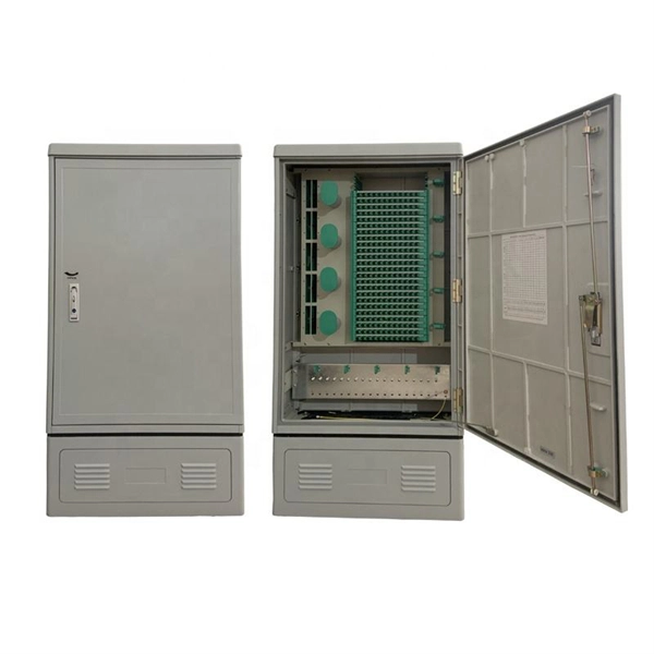
A typical fiber optic splice enclosure consists of several key components that work together to protect and organize the fiber splices. Standard enclosures contain: 1) Housing, 2) Cable fixation clamps, 3) Splice trays, 4) Sealing system. A splice box (also known as splice distributor) is a housing in which fiber optic cables begin or end. Fiber optics are fanned out in splice boxes that are situated at the end of fiber optic transmission paths. Optical cable joint box The optical cable joint box permanently connects two optical cables together and has a joint part for protecting components. The optical cable connection part, that is, the optical cable joint, is the part where the. An optical cable split fiber box, also known as a fiber distribution box or fiber optic splice closure, is a device used to terminate, splice, and distribute optical fibers. In this response, we will focus on the. This guide optimizes the original text by delving deeper into the three pillars of fiber network longevity: the impact of splicing technology, the strategic selection of splice boxes, and the essential maintenance protocols needed to ensure sustained, high-speed functionality. Fibre optic cables are manufactured in standardized lengths –.
[PDF]

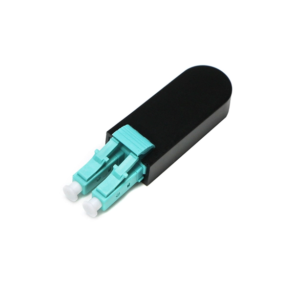
Its typical transmission distance is 20km or 40km. For instance, some ethernet switch manufacturers refer to the 1000BASE-LH SFP as the 1G 1310nm 40km SFP transceiver, which indicates the module's transmission distance and wavelength. The 10G SFP+ dual-fiber optical module is a small pluggable optical transceiver that adopts a dual-fiber bidirectional design. It completes signal transmission (Tx) and reception (Rx) through two independent optical fibers, ensuring the stability and reliability of signal transmission. An SFP (Small Form-factor Pluggable) module transmits data over fiber using specific wavelengths and power levels, which directly influence how far the signal can travel before degradation occurs. This is why two. If the optical module works at a wavelength near 850nm (880nm) or 910nm (940nm), then the module is a multi-mode fiber (MMF) optical transceiver, and if the working wavelength is 1310nm or 1550nm, it is a single-mode fiber (SMF)optical module. Generally, the maximum transmission distance(generally. The transmission distance of optical transceiver modules is divided into short distance, medium distance, and long distance. A 1-core module uses a single fiber core for data transmission, while a 2-core module uses two cores. o Think of a highway. Chromatic dispersion This is a key factor affecting single mode fiber distance.
[PDF]
It can be seen from the above that the aggregation switch has functions such as source address, destination address filtering, real-time policy, security, network isolation, and segmentation. Compared with access switches, aggregation switches have better performance and higher. What is an Aggregation Switch and How Does it Work? An aggregation switch consolidates data traffic from multiple network access switches into a single high-bandwidth link directed toward a core network or data center. The primary function of an aggregation switch is to aggregate and forward data. A fiber optic aggregation switch is a high-capacity network device designed to integrate and manage multiple fiber optic connections from access layer switches into fewer and faster uplink connections to the core network. It is essential for larger networks requiring efficient data flow. You may also. All-optical Ethernet switches are a type of switch that provides optical uplink and downlink ports, making them an ideal choice for building an all-optical campus network. They can function as core, aggregation, and access devices on campus networks and connect to upstream and downstream devices. As the physical entity of the aggregation layer, the aggregation switch's primary function is to aggregate the data of the access layer switch and forward it to the core switch to reduce the burden on the core layer. Cisco's aggregation switch What is the Role of the Aggregation Switch in the.
[PDF]
Fiber optic cables have revolutionized the way we transmit data, offering greatly improved speed and reliability compared to traditional copper cables. These cables use light to carry information, resulting in faster and more efficient communication. A TOSLINK optical fiber cable with a clear jacket. A fiber-optic cable, also known as an optical-fiber cable, is an assembly similar to an electrical cable but containing one or more optical fibers that are used to carry. What is DSL internet? Obsolete in most populated areas, DSL delivers internet using traditional telephone lines. It's different from the old-school dial-up of yesteryear, as you can use the internet and your landline at the same time, but it's still one of the older technologies out there. The process relies on a principle called Total Internal Reflection. What is Fiber Optic Cable? A Fiber Optic Cable is used to transmit data through fibers (threads) or plastic (glass). This pack of glass which is within sorts of threads transmits modulated messages along sunshine waves. There are many advantages of using these cables over other kinds of. Fiber-optic cables on cable drums are versatile. They are used wherever a glass fiber connection is temporarily required. For any kind of events, e. Trade fairs, sports events, conferences, filmed productions, etc. High-Speed Transmission: Fiber optics use light.
[PDF]
Cable laying services install fiber optic cable or copper cable in buildings and office complexes, or over large distances. They are staffed by cable technicians who perform cable preparation, jointing, termination, testing, commissioning, maintenance, and troubleshooting tasks. Installing fiber optic cables underground involves far more than digging trenches and placing cables. It forms a critical backbone for modern communication networks across both urban and rural environments. Project success depends on careful planning, precise installation practices, and proper. Installing underground fiber optic cables is critical to establishing high speed internet infrastructure that delivers reliable connectivity for businesses nationwide. Unlike traditional copper systems, fiber optic cables require specialized handling techniques and precise installation methods to. These skilled professionals ensure that your home or business is equipped with the latest fiber optic technology, providing blazing-fast Internet speeds and robust connections. This guide walks you through the entire process of fiber cable installation, from the initial assessment to the final. This involves burying or installing fiber-optic cables along predetermined routes. During this phase, locators identify existing utilities to prevent damage.
[PDF]