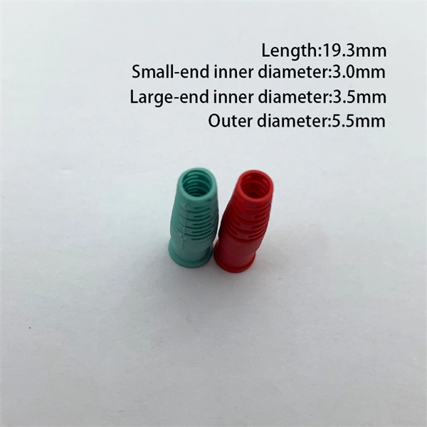
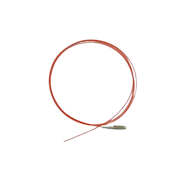
The operation and skills of fiber optic fusion splicing technology can be mainly divided into five steps: fiber stripping, fiber cutting, fiber melting, fiber sleeve, and fiber winding. Two types of splices are used in fiber optic cabling one is Mechanical the other is Fusion. And tools used for fiber fusion: fusion splicer; fiber cleaver; cable stripper; fiber optic stripper; alcohol;. These specialized devices are engineered to manipulate, terminate, join, and verify light-carrying strands without introducing microscopic fractures or contamination. At Weunion, we categorize these essential instruments into four primary operational phases: Preparation: Removing protective layers. Various techniques can remove the coating: Regardless of the method used to strip the coating, it is important to use the correct tools and techniques to prevent damage to the bare glass. Ensuring the fiber. What is Fiber Optic Splicing and Why is it Needed? – #1. Use and Maintain Your Cleaver Correctly – #3. Set Your Fusion Parameters in a Systematic Way What is Fiber Optic Splicing and Why is it Needed? First, let us understand the meaning of the term. Fusion splicing joins two optical fibres end-to-end using heat, creating a seamless connection for minimal signal loss. owever, proper cable preparation is essential before firing up your fusion splicer. A poorly prepared fibre can lead to weak splices, high attenuation, or complete failure.
[PDF]
Cablofil cable tray is the preferred choice for the cable containment of low and high voltage electric cables where fire resistance is crucial - this includes cable basket tray systems for Prysmian FP (FP400 and FP600) and Draka Firetuf type cables. Cable trays hold the wires for things like power and communication. Fire protection systems find fires, raise the alarm, control the fire, and put it out. They seem like separate things, but they need each other to keep buildings safe. We will look at how these two systems team up to make sure. Protects critical power and signal cables in case of fire, maintaining their integrity and functionality. The prefabricated design consists of modules joined together with eccentric locks or tightening bands. This. Cable tray fire protection: Go onto any rig, into any petrochemical plant, factory, production plant, hospital, office or wherever power, communications and data are essential and you will be surrounded by cable trays. Unnoticed by most people, they house the power cables and data cables. Cablofil fire resistant and fire proof cable. Electrical cable tray wall penetration firestopping Scope: Firestopping for busway, cable trays, cables, and trunking passing through walls in enclosed electrical installations. Where cables pass through shafts, walls, slabs, or enter electrical panels or cabinets, openings shall be tightly sealed.
[PDF]

A good laser source for a singlemode link will have a power output of ~ +3 to +6 dBm - 2-4mw - coupled into the fiber. Tx power (transmission power) refers to the intensity of the optical signal output by the transmitting end of the optical module. However, in practical use, we adopt the average Tx power. These modules, including SFP, SFP+, and SFP28, are widely used in enterprise networks, data centers, and carrier-grade deployments. Optical loss is measured in “dB” which is a relative measurement, while absolute optical power is measured in “dBm,” which is dB relative to 1mw optical power Loss is a negative number (like –3. 2 dB) while power measurements can be either positive (greater than the reference) or negative (less than. SFP (Small Form-Factor Pluggable) modules are compact transceivers that allow for high-speed communication between network devices. They are essential in applications like telecommunications, data centers, and enterprise networks. Generally, the power levels are specified in terms of transmit (TX) power and. Transmit power is the power at which the transmitter of an optical transceiver module transmits optical signals in dBm. When the signal received is outside of the range, there is a.
[PDF]
A temporary power box, also known as a power spider box, is a portable electrical enclosure that provides temporary electrical power distribution on construction sites and other remote locations. It serves as a hub for connecting various electrical loads and distributing power. Temporary construction power system s are essential for delivering safe and reliable electricity across dynamic job sites. From powering heavy machinery to supporting lighting and tools, temporary power boxes must operate in harsh outdoor conditions while ensuring electrical safety and flexibility. These panels act as the central. Temporary power distribution boxes provide a safer way to manage power while keeping your workspace tidy. These versatile units work great for construction sites, entertainment events, and disaster recovery operations. You can use them to power electrical equipment, lighting systems and more. Unlike permanent power solutions that are integrated into a building's.
[PDF]

Cable Trays* — Max two 24 in. (610 mm) wide by max 6 in. (151 mm) deep open-ladder cable tray with channel-shaped side rails formed of 0. 54 mm) thick aluminum or min 0. In practice, cable tray dimensions are a system of interrelated measurements —width, depth, length, and material thickness—that directly affect cable fill compliance, heat dissipation, structural loading, and long-term expandability. From an engineering standpoint, cable tray dimensions are not. Perforated Cable Tray System expertly constructed from high-grade stainless steel, offering exceptional durability and resistance to corrosion. With side height 100mm. A properly designed and installed cable tray system will provide. Studs — Wall framing to consist of wood studs or channel shaped steel studs. Wood studs to consist of nom 2 by 4 in. Additional studs shall be used to completely frame. Best Size: Here, deep trays (75mm to 150mm) are used since power cables are typically thick and heavy. Data cables, such as your Wi-Fi or computer ones, are extremely sensitive. They do not get hot; however, they do not like to hang or sag. In case a data cable folds in an excessive manner, the. ect the minimum bend ra-dius for cables as they exit the bottom of the cable tray. A rung spacing of 6 to 9 inches (150 to 230 mm) is preferable when the cable tray cont d for instrumentation and control applications that require additional protec eferred to support and protect numerous small.
[PDF]

A ladder type cable tray tee is a fitting used to create a branch in a cable tray system, allowing cables to be routed in three directions. Its "T" shape provides a secure and efficient way to split cables from a main tray into two separate paths, ensuring organized and flexible. A cable tray tee and tee cover are components used in cable management systems to support and protect electrical and data cables. Here's a brief explanation of each:. Rigid steel cable tray tee fitting with zero tangent, safety bottom, and full accessory support. ventilation to heat producing cable such as power communication and other with the same or different width of the cable run. All fittings are available in sizes and types corresponding to the straight cable tray sections. These fitting are including: elbow, horizontal cross, vertical inside. NOTE : Equal or un equal tees can be supplied. When ordering state widths W1xW2xW3.. Office: 147/22 Nguyen Sy Sach Street, 15 Ward, Tân Binh Dist, HCMC,VN. Is it possible to connect 2 cabletrays with a "branch piece (left picture)" instead of a "tee (right picture)". The tee has 3 connectors, the branch piece only has 1 connector. I would like to ajust the "Type properties -> Fittings -> Tee" with the branch family, but can't get it accomplished.
[PDF]

An Optical Splitter, also known as a beam splitter, is a passive optical device that divides a single input optical signal into two or more output signals. Conversely, it can also combine multiple signals into one. Knowing the difference between a splitter and an optical coupler helps you build better networks. You make your network work better when you pick the right device for each job. You can connect many users to one port with 1:n or 2:n splitters. By dividing a single optical signal from a central Optical Line Terminal (OLT) into multiple outputs for Optical Network Terminals (ONTs) at users' homes, splitters eliminate the need for dedicated fibers to each residence—slashing infrastructure costs while scaling network reach. This guide. In a Passive Optical Network (PON), a single optical fiber carries massive amounts of data using light. Signal Input: The fiber splitter receives the optical signal from the upstream network node and enters the splitter through the input fiber. Signal Distribution: Inside the splitter, according to the design structure and different. Splitters are passive optical devices that divide or combine optical signals, and they come in various types, including power splitters, uneven splitters, and wavelength-division multiplexing (WDM) splitters. Each type serves specific applications, enabling efficient use of optical infrastructure.
[PDF]

A protective relay is an intelligent electrical device designed to detect faults in power systems and initiate corrective actions such as tripping a circuit breaker. · Detection of the presence of a fault. · To close the trip circuit and operate the circuit breaker to isolate the faulty system from the healthier one. What is a protection relay? What is the purpose of protection. An electrically operated switch like a relay plays a key role in controlling an electrical circuit through an independent low-power signal, otherwise used where a number of circuits should be controlled through the single signal. Its main purpose is to safeguard electrical equipment like transformers, generators, and transmission lines from damage due to. A protection relay is a crucial component of electrical systems that safeguard infrastructure, employees, and equipment from electric problems and malfunctions. It functions as a watchdog by constantly surveying multiple system components including voltage, current, frequency, and phase angle. In other words, the prime function of protective relays is the timely and.
[PDF]
Housing Integrity: Cracked, melted, or physically broken outer casings. Electrical Failure: Severe internal burn marks or "fried" traces that prevent a safe rebuild. Completeness: Units that have been scavenged for internal parts or are missing proprietary hardware. This document describes how to identify, isolate, and troubleshoot symptoms of hardware failures on Catalyst 9600 Supervisors and Line Cards. There are no specific requirements for this document. The information in this. If the switch has rebooted unexpectedly, you can follow the steps to troubleshoot the hardware. If your core looks different. This topic covers the steps for troubleshooting bootup, crash, network, software, and audio issues related to the Q-SYS Core 110f processor and Cinema Core 110c processor. It details what information to collect post-event to help identify the root cause. Requirements and Components Used Requirements: None specific to hardware/software versions. Lab. Hardware faults on CE switches include power supply faults, fan faults, card power-on failures, unexpected card restarts, abnormal optical module status, and abnormal interface status. The following information helps you quickly locate hardware faults. Common Causes of Power Supply Faults Common.
[PDF]

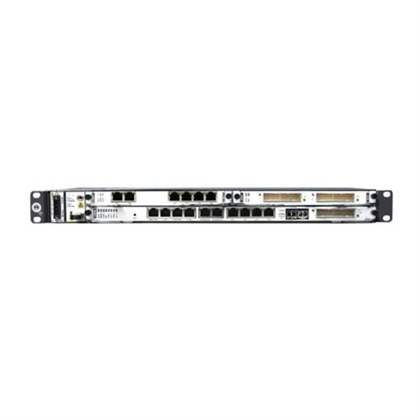
This article will introduce passive optical networks (PON), in which we will introduce everything about OLTs, ONTs, ONUs, and ODNs, including their operation principles and functions. PON (Passive Optical Network) refers to a fiber optic network built using a point-to-multipoint topology and fiber. Active Optical Networks (AON) and Passive Optical Networks (PON) make FTTH broadband connections possible. To date, most FTTH deployments in planning and deployment have used PON to save on fiber costs. PON has attracted much attention in recent years due to its low cost and high performance. There are no specific requirements for this document. This document is not restricted to specific software and hardware versions. The information in this document was created from the devices in a. OLT, ONU, ONT, and ODN are key components and acronyms used in Passive Optical Network (PON) architecture, which is a popular technology for delivering high-speed broadband services. This technology is widely used in fiber-to-the-home (FTTH) and fiber-to-the-premises (FTTP) deployments. In contrast to AON, multiple customers are connected to a single transceiver by means of. An Optical Distribution Network (ODN) serves as the bridge in a Passive Optical Network (PON), transmitting optical signals from the Optical Line Terminal (OLT) to the Optical Network Unit or Terminal (ONU/ONT), thus linking a service provider's core network to end-users (residential or business).
[PDF]

In this complete wiring diagram guide, we will walk you through the step-by-step process of wiring a mag starter. We will explain the purpose and function of each component, provide clear diagrams, and offer expert tips to ensure a successful installation. Whether you're a beginner or an. For proper integration of an electromagnetic securing device, ensure the power supply matches the specified voltage–typically 12V or 24V DC. Incorrect voltage can cause malfunction or reduced holding force. Use a regulated power source to prevent current fluctuations that might trigger false alarms. Understanding the wiring diagram of a magnetic starter is essential for technicians and electricians who work with electric motors. This diagram provides a visual representation of the components and connections involved in the operation of the starter. Once you have everything ready, you can proceed with the installation process. Begin by determining the appropriate position for the magnetic lock on the door. Quick guide on how to wire an access control system with power supply, lock, and exit button. more Quick guide on how to wire an access control. Installing a magnetic door lock can be a cost-effective and reliable way to secure your doors. These locks use an electromagnetic current to keep the door securely closed, and they are commonly used in commercial and residential buildings.
[PDF]
Voltage droop is the temporary reduction in the output voltage of a power source that occurs when the system suddenly draws a significant amount of electrical current. This drop is a fundamental consequence of electricity moving through materials that are not perfect conductors. The sudden increase. Voltage anomalies in telecom power systems disrupt network stability, often causing unexpected outages and costly downtime. Operators face significant challenges when faults go undetected, risking both equipment and service reliability. Power-related failures account for nearly one-third of telecom. Voltage stability in power systems can be impacted by various disturbances; including faults, load changes, equipment failures, and weather events. Instability can cause severe issues like loss of load, cascading outages, and the loss of synchronism in generators. Every conductor, regardless of material or size, possesses some amount of resistance that impedes current flow and converts electrical energy. Voltage dropping is a power quality condition where voltage at equipment terminals falls below expected operating levels during load conditions, causing instability, fluctuating performance, and observable changes in electrical system behavior. It is dynamic, load-driven, and often intermittent. Voltage drops and power losses in power lines are common and normal phenomena. They are associated with the flow of current through the different network components.
[PDF]
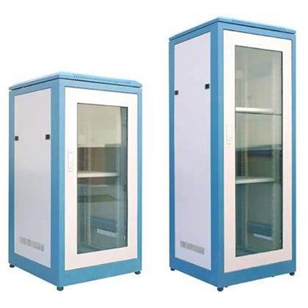
The enclosure is made of bent steel plates, featuring a compact structure, easy maintenance, and flexible circuit scheme combinations. Besides air circuit breakers and fuses for circuit protection, the distribution cabinet can also be equipped with contactors and thermal relays. Mauritius power strips and PDU power distribution units for surface mount, rack mount and general purpose applications. Multiple outlet power strips are manufactured in accordance to Mauritius standards with agency approvals. Designed for safety and durability, our range includes solutions for residential, commercial, and industrial electrical setups in Mauritius. Practibox S surface mounting cabinet with earth terminal blocks -. Mauritius is one of the world's most renowned island destinations, attracting millions of visitors each year with its tropical beaches, luxury resorts, and vibrant tourism industry. Behind the smooth operation of hotels, restaurants, and resort facilities lies a critical requirement: stable and. The transmission and distribution system forms the backbone of electricity supply in Mauritius, ensuring reliable power delivery from generation facilities to customers across the island. How the System Works Electricity is transmitted at higher voltages from generation sources to Bulk Supply. The XL type low-voltage power distribution cabinet uses domestically designed new components. The answer lies in upfront. Meta Description:.
[PDF]
By studying the expansion of Chinese telecommunications companies abroad, with a particular focus on Africa in our case study, the chapter aims to explore the relationship (i. partnership or/and competition) between African and Chinese telecommunications in. Chinese telecom infrastructure in Africa has expanded rapidly, embedding Beijing's influence into the continent's digital backbone. Upholding the principles of sincerity, real results, amity and good faith, China and African countries have achieved notable outcomes in infrastructure cooperation. Africa is China's. Chinese involvement in Africa's telecoms sector predates the DSR. The global advance of Chinese telecommunications firms, such as Huawei and Zhongxing Telecom Ltd (ZTE), was largely enabled by China's “go out policy,” which was launched in 1999 with the aim of promoting the internationalization of. According to the Tech Review Africa and Chinese Xinhua News, China Mobile officially activated 2Africa East Segment Submarine Cable on November 7, 2025, with an aim to power digital transformation across the African continent. The 2Africa submarine cable system, which spans 33 countries across. Infrastructure cooperation between China and Africa is thriving, and the outcome is changing the lives of millions. Industrial leaders and officials observed that the infrastructure projects undertaken by Chinese companies have yielded tangible benefits for Africans, helping the continent enhance.
[PDF]
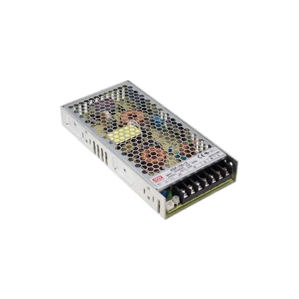
This paper presents a new liquid-cooling technology for uninterruptible power supply (UPS) units in which an air-cooling system is combined with an indirect water-cooling system based on direct-chip coolin.
[PDF]