Fusion splicing is most widely used as it provides for the lowest loss and least reflectance, as well as providing the most reliable joint. Virtually all singlemode splices are fusion. 📦 For purchasing, use the RP Photonics Buyer's Guide for fiber cleavers. It provides an expert-curated supplier directory, buyer-focused technical background information, and structured selection criteria to support professional procurement decisions. In many applications of fiber optics, it is. The fiber optic quick connector/cold connector is a very innovative field-terminated connector, which contains factory-installed optical fiber, pre-polished ceramic ferrule and a mechanical splicing mechanism. The incoming optical fiber or indoor optical fiber can be inserted into the mechanical. A reliable fiber-optic network depends on more than selecting the right cable and connectors; it hinges on the quality of every splice. In fact the splice shall ensure high quality and stability of performance with time. Either joining method must have three primary characteristics. Fiber joints are the points where two optical fibers are permanently connected to create an uninterrupted transmission path. These connections are essential in fiber optic networks, enabling the extension, branching, or repair of fiber cables while ensuring minimal signal loss during transmission.
[PDF]
The connectors used in cold splicing typically consist of two parts: a ferrule and a body. The ferrule is a small, cylindrical piece that is designed to hold the fiber in place and maintain its alignment with the other fiber. Optical fiber cold splice technology is based on the use of mechanical connectors to join two fiber-optic cables. Get the wrong connector type, the wrong polish, or skip proper fusion splicing technique—and you're looking at elevated signal loss, increased back reflection, and a. Fiber optic joints or terminations are made two ways: 1) splices which create a permanent joint between the two fibers or 2) connectors that mate two fibers to create a temporary joint and/or connect the fiber to a piece of network gear. This is essential for extending network reach, repairing breaks, or connecting cables in data centers and telecom infrastructure. The goal is to align the microscopic glass cores (typically. In this guide, we cover the basics of fiber optic splicing, how to perform splicing using two different methods, and finally some best practices to perform good fiber splicing. What is Fiber Optic Splicing and Why is it Needed? – #1.
[PDF]
This Cable Sizing Calculator can calculate minimum active, neutral, and earth cable sizes in compliance with the international standard IEC 60364-5-52. It covers all cable types, installation methods, and correction factors in the standards. This guide provides a detailed explanation of cable sizing, including formulas, examples, and tips to help you make accurate decisions for any project. The correct cable size ensures: Safety: Prevents overheating and potential fire hazards. Efficiency: Reduces energy losses due to resistance. Professional electrical wire sizing tool based on National Electrical Code (NEC) standards. Calculate proper wire gauge, voltage drop, and ampacity for safe electrical installations. Input your electrical parameters to get accurate wire size. The calculation follows IEC 60364-5-52 and BS 7671 standards. Selecting the correct conductor cross-sectional area (mm²) is fundamental to electrical safety and system performance. Undersized cables can lead to: Energy inefficiency: Higher I²R losses increasing operational costs. You can estimate. This article examines the sizing of electrical cables (i. cross-sectional area) and its implementation in various international standards. IEC, NEC, BS, etc) and some standards emphasise certain things over others. This cable sizing standard applies to circuits up to.
[PDF]

This quick-reference guide focuses on what to measure, how to interpret results, and what to do when findings indicate marginal performance. Whether you're a network engineer validating new inventory or an integrator preparing for deployment, knowing how to test optical transceiver modules can save time, reduce failures, and ensure SLA compliance. Unchecked optical modules can cause: Testing ensures compliance with IEEE 802. 3 and MSA. This article provides a comprehensive guide on measuring key performance indicators to evaluate the functionality of optical modules, with a specific focus on the sfp28 transceivers. A comprehensive understanding of the working principle of an optical module is essential for determining the. Evaluating the performance of optical modules is a practical discipline: you must verify optical power and signal quality, confirm electrical/optical compliance, validate link-level behavior under real traffic, and document results in a way that supports reliability engineering. This. The optical module serves as a crucial component in optical fiber communication systems, operating at the physical layer, which is the lowest layer in the OSI model. Its primary function is to achieve optoelectronic conversion by converting electrical signals into optical signals and vice versa.
[PDF]

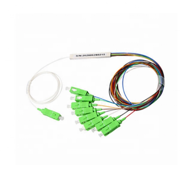
While most pigtails are single-fiber, multi-fiber options exist: Single-fiber: The most common (LC, SC, FC). Multi-fiber: 2, 4, 6, 12, 24, 48, or 72 fibers. Multi-fiber pigtails often come in ribbon format for splicing into high-count cables. Traditional Fusion Splice-On Connectors with pigtails provide factory-polished performance with field-termination convenience within harsh environments. Mass fusion splicing can fuse up to all 12 fibers in one ribbon at once. Mass Fusion Pigtails come with all 12 fibers terminated and a ribbonized. By fiber type, there are single-mode fiber optic pigtail and multimode fiber optic pigtail. And by fiber count, 6 fibers, 12 fibers optic pigtails can be found in the market. Fiber pigtails are used in an estimated 99% of single-mode fiber applications worldwide. Despite this ubiquity, they remain a source of confusion for procurement teams and junior installers alike—especially when it comes to connector type selection, polish type, and the tradeoffs between mechanical. Fiber optic pigtails can be divided into single-mode and multimode fibers. Conversely, multimode fiber pigtails, usually orange, use a 62. 5m to 2m—that has a factory-terminated connector on one end and bare fiber on the other end. The connector end is polished and tested under factory conditions, ensuring low insertion loss and high return loss.
[PDF]
Wiring a 3-way junction box involves connecting three separate wires: the hot wire, the traveler wire, and the neutral wire. Here is a step-by-step guide on how to wire a 3-way junction box. In a 3-way junction box, multiple wires can be joined together for the purpose of distributing power or connecting different electrical devices. Whether you are a professional electrician or a DIY enthusiast, understanding how to properly wire a 3-way junction box is essential for maintaining. In this article, we'll take a look at what you need to do in order to wire a 3-way junction box and provide you with some useful tips to make the process easier. In this comprehensive guide, we. Learn how to install a junction box safely, from choosing the right box and mounting it correctly to making secure splices and following basic code-safe practices. To install a junction box correctly, choose a box that matches the wiring method and environment, mount it securely, bring cables in. A three wire junction box is an essential component in electrical installations that allows for the connection and distribution of electrical wires. It provides a safe and convenient way to connect multiple wires, ensuring proper electrical continuity and reducing the risk of electrical hazards. We may be compensated if you purchase through links on our website. Our team is committed to delivering honest, objective, and independent reviews on home.
[PDF]
Shipping cost not included. The 144 core aerial fiber splice closure is a high-capacity outdoor enclosure designed to provide reliable fiber splicing, joint protection, and distribution for aerial and pole-mounted applications. Check each product page for other buying options. Price and other details may vary based on product size and color. Need help?. An Optical Ground Wire (OPGW) splice box is a critical component in power and telecommunications infrastructure, designed to protect and organize fiber optic splices within overhead ground wires. These boxes ensure signal integrity, mechanical protection, and environmental resistance for fiber. ZIP code to view pricing. ZIP code to view pricing.
[PDF]

Fiber optic network design (896. 83 KB). I'm needing symbols for common fiber optic components, cables, connectors, backbone ports, etc. Can anyone help me out? Some examples of a diagram would also help. 10-27-2018 01:41 AM Do you know if there's some symbol standard fir this kind of schematics? I surely don't know. If you can be helpful. Free CAD and BIM blocks library - content for AutoCAD, AutoCAD LT, Revit, Inventor, Fusion 360 and other 2D and 3D CAD applications by Autodesk. CAD blocks and files can be downloaded in the formats DWG, RFA, IPT, F3D. You can exchange useful blocks and symbols with other CAD and BIM users. See. Search by part number or description such as CAT5, CAT6, OSP, etc. Sort by any of the table headers. Use the drop down menu to filter by product category and type. Sort by any. Welcome to the Corning LANscape® Solutions Product Drawings Resource Center, your complete source for our optical hardware component drawings. The two-dimensional and isometric hardware products drawings are available in PDF (Adobe® Acrobat®), DXF (AutoCAD®), VSS (Visio® Stencil) formats, and. Be among the first to receive important product updates, insights and news. Of all these options, the most favored one is optical cables because they offer uninterrupted swift data transmission.
[PDF]
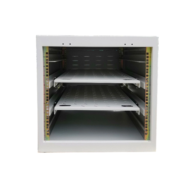
The number of ports in a fiber optic termination box varies from 8 to 96 ports, so you can choose the right junction box for your cable needs. The optical fiber terminal box is the terminal connector of the optical cable, one end is the optical cable, and the other end is the optical cable tail. A Multiport Service Terminal is a hardened, environmentally sealed enclosure that provides multiple pre-connectorized output ports (typically 4, 8, 12, or 16) for drop cables, while accepting a single incoming feeder or distribution cable. Key characteristics: MST boxes are the cornerstone of. The terminal box is a fiber management product used to distribute and protect optical fiber links in FTTH networks. This ethernet port is used to connect the modem to an internet router. Modem router combo devices will generally have four ethernet. A router is more than just a box with blinking lights—it contains multiple ports, each tailored for specific roles, such as LAN, WAN, USB, DSL, and console ports. Understanding the purpose, specifications, and configuration of these ports is essential for achieving maximum network performance. It is also sometimes referred to as an "ONT box" or "fiber box. " What Does an ONT Do? Key Functions Explained Here's a quick breakdown of what an ONT does: The ONT receives light signals from the fiber network and converts them into electrical signals.
[PDF]

View price, stock and buy direct from Transceiver USA. Customize your 1/10/25/100/200/400G transceiver from data rate, connector type, compatilibity to form factor. With well-equipped lab, all FS custom optical transceivers are produced with high-quality components, offer a five-year warranty and fast shipping. Purchase from nearby warehouses. This article compares typical cost ranges across speeds and transceiver types, explains why prices vary, and gives practical guidance for choosing the right optics for a given. This post offers quick access to the SFP module price list by researching top vendors. SFP modules have been in large demand in data centers with the continuous development of optical communication. Also, the SFP module type upgrades rapidly. It has been experienced from the initial version of 1G. Optical Transceiver Modules/SFP, also called fiber optic transceiver or optical transceiver, is a typically hot-pluggable device used in high-bandwidth data communications applications. While optical transceiver development has gotten simpler over the years, it does involve full engineering development to design, validate, and qualify. Generally, the two main milestones in this phase are. An Optical Transceiver is a critical optoelectronic component that facilitates seamless electro-optical (E-O) and photo-electric (O-E) conversion within fiber-optic networks.
[PDF]

How to hardwire a Self-Regulating heat cable into a junction box, with a tutorial of the final end seal. First thing, get the sealing ring and connect it onto the connector body. Make sure it gets onto the very e. Safety comes first, and clear info makes it doable. Know Your. We'll show you how to size the heater, run a new, safe 240-volt circuit and install a programmable thermostat. Most homes have sufficient capacity for the new circuit in the service. If you're working with heating cables, understanding how to connect them safely and efficiently is crucial. In this guide, we'll break down the steps in simple terms. Whether you're a DIY enthusiast or a professional, this article is here to help. Stay safe and ensure proper installation with these. I need help wiring an electric furnace with heat elements. I ran number 6 wire with ground from my 100 amp service box where I installed a 60amp double pole breaker. The furnace comes with an other set of breakers one 60amp and one. A distribution board or distribution box is where the main power supply is distributed to multiple loads. Single Phase Distribution Box generally consists of Double Pole MCBs, Single Pole MCBs, and RCCBs.
[PDF]
In this article, we will explore the six proven ways to fix optical cable issues, enabling you to get back to enjoying high-quality sound and visuals without a hitch. Before delving into troubleshooting, it's useful to understand exactly what an optical cable is and how it works. Optical cables, often referred to as fiber optic cables, have become integral to our everyday lives, delivering high-speed internet and crystal-clear audio and visual signals. However, like any technology, issues may arise, leading to anxiety and frustration when your optical cable isn't. Whatever the case, In this article, we have discussed the fixes that you can apply when your optical cable is not working. Since a damaged optical cable will prevent you from using your external speakers, you need to solve it as soon as possible. These cables are made entirely of dielectric materials, such as. Optical cables have revolutionized how we transmit audio and visual signals, providing a crisp connection with minimal interference. They use light to carry data, making them an excellent option for connecting devices like televisions, sound systems, Blu-ray players, and gaming consoles. However. While a cut or damaged fiber optic cable can temporarily take your network down, it is possible to quickly fix the cable with the right tools. This wikiHow article will teach you how to splice a cut fiber optic cable back together with a fiber optic stripper and cutter and a fiber optic crimper.
[PDF]
If you find there is no ground wire in your electrical system, consider replacing outdated two-prong outlets, installing Ground Fault Circuit Interrupters (GFCIs), or exploring grounding through metal conduit or armored cable. Electrical grounding is a fundamental safety mechanism that provides a low-resistance route for fault current to return to the source and trip a circuit breaker or fuse. This pathway prevents metal casings of appliances and tools from becoming energized with hazardous voltage during an internal. It's possible that there's a ground wire that's connected to the box, but if this is original 1948 wiring, that's unlikely. If there's been a wiring update since, it's possible. As noted above, a GFCI receptacle is now required in the kitchen and installing them adds protection even if they're not. A ground wire can be connected to an electrical junction box if no place is available for its attachment. It is extremely important not to cut the ground wire. In this comprehensive guide, we will walk you through the steps to. If you cannot find a ground wire, use this instruction to add one to the panel. The process involves the following: 1). Therefore, before installing the ground wire, you should first plant the rod. You only need three. Is it OK not to connect the ground wire? It is entirely possible for an electrical device to not use the ground. Especially for low-power devices, such as routers, mobile phone chargers, small lamps, and so on.
[PDF]
Learn how to properly install a pigtail connector in just a few easy steps. No description has been added to this video. Enjoy the videos and music you love, upload original content, and share it all with friends, family, and the world on YouTube. Pigtail connections are most frequently used to ground a switch or electrical outlet and for electrical devices that need to connect to multiple circuit wires. They also come in handy to lengthen circuit wires that are too short to reach a device. A pigtail is composed of three strands of wire. A pigtail connector is a short length of insulated electrical wire that is pre-attached to a device, terminal, or fixture, serving as a flexible bridge between the fixed wiring system and the component. Whether you are a DIY enthusiast or someone facing an electrical issue, understanding how to replace a pigtail connector can be invaluable. This article will walk you through the necessary steps and provide. This is where quality automotive connector replacement steps in. Often, rather than pay thousands of dollars for an entire harness, you can simply replace the damaged connector by a careful de-pin/re-pin or an accurate wire repair. Want more automotive electrical wire repair videos? Click Here Hear. The National Electrical Code (NEC) requires a pigtail to be at least six inches long. Although this standard applies to house wiring, we can use the same for vehicle wiring.
[PDF]
The cost to install fiber optic cable ranges from $1. 50 to $42 per foot, with installation costs accounting for 60-80% of total project expenses. According to the Fiber Broadband Association's 2025 report, median costs are $8 per foot for aerial builds and $18 per foot for. Homeowners and businesses typically pay for fiber optic cable installation based on distance, conduit needs, and labor. The main cost drivers include material type, run length, trenching or aerial work, and any required permits or inspections. This article outlines cost expectations. The initial cost of installing fiber optic cables can vary depending on the chosen installation method and specific project requirements. fiber projects, we've assembled current material rates, labor burdens, and hidden fees. Whether you need singlemode, armored, or indoor plenum, this guide gives you the exact cost per foot of fiber optic cable —. Fiber optic cable installation costs between $1,500 and $7,000 for your home, with prices varying by cable length and installation method. The installation type you choose and the layout of your property determine the total labor and materials needed for your project.
[PDF]
