Picking up the best router for fiber internet isn't just about going to the market and choosing one of the best wireless routers. Instead, you need to carefully look at its specs, performance, and the type of securit.
[PDF]
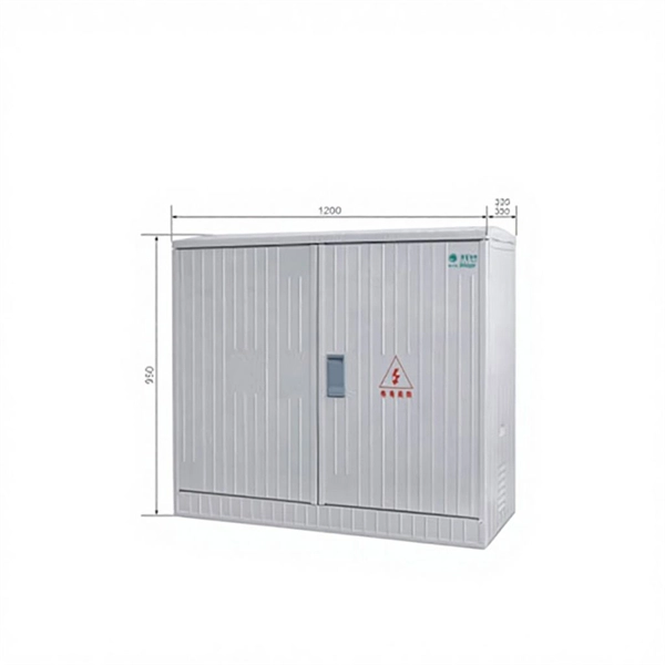
What Is an Explosion Proof Junction Box? An explosion proof junction box is a sealed electrical enclosure designed to contain sparks or flames that may occur within the box, preventing them from igniting explosive gases or dust in the surrounding environment. Explosion-proof electrical distribution boxes are essential for safety in hazardous environments. These specialized enclosures are built to contain internal explosions and stop the ignition of flammable materials. In this article, we will explore three key aspects:. Explosion-proof enclosures are used by such facilities to ensure the safe housing of electrical components that could cause a spark and ignite these gases in the atmosphere. What Is An Explosion Proof Box or Enclosure? They are a cast aluminum or iron box that can withstand a heavy-duty explosion. Specification code(I,II,IIB. Flameproof enclosure (Ex d IIB+H2), which can be used as feed distribution equipment in control and distribution system (such as distribution box, switch box of main circuit, control box, terminal box or motor starting box etc. ) ·Enclosure: stainless steel. Equipped. (a) A cable passing through an outside wall (s) of a distribution box shall be conducted either through a packing gland or an interlocked plug and receptacle. (b) Short-circuit protection shall be provided for each branch circuit connected to a distribution box. The current-carrying capacity of the.
[PDF]

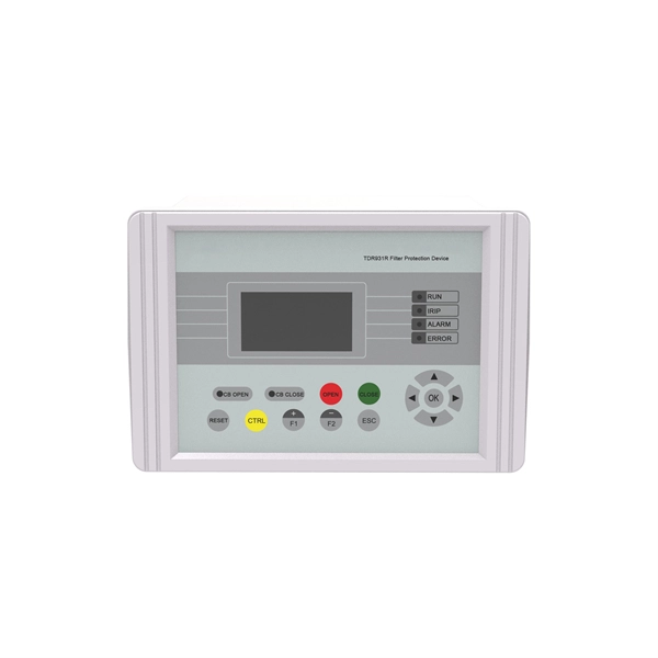
A protective relay is an intelligent electrical device designed to detect faults in power systems and initiate corrective actions such as tripping a circuit breaker. · Detection of the presence of a fault. · To close the trip circuit and operate the circuit breaker to isolate the faulty system from the healthier one. What is a protection relay? What is the purpose of protection. An electrically operated switch like a relay plays a key role in controlling an electrical circuit through an independent low-power signal, otherwise used where a number of circuits should be controlled through the single signal. Its main purpose is to safeguard electrical equipment like transformers, generators, and transmission lines from damage due to. A protection relay is a crucial component of electrical systems that safeguard infrastructure, employees, and equipment from electric problems and malfunctions. It functions as a watchdog by constantly surveying multiple system components including voltage, current, frequency, and phase angle. In other words, the prime function of protective relays is the timely and.
[PDF]
Usually, the 10G/25G grey light optical modules with a short transmission distance are applied for connecting AAU/DU with WDM/OTN/SPN. The connections between WDM/OTN/SPN network devices can be achieved by 10G/25G/50G/100G dual-fiber or single-fiber bidirectional. Compared with Draft A (2013-07-30), this issue includes the following new topic: 2. This section describes engineering specifications of an AAU, including input power and equipment specifications. 7. In 2/3/4G networks, 10Gbps optical modules are generally enough for CPRI interfaces. In 5G networks, CPRI is also upgraded to eCPRI. Currently, 5G of the bearer network mainly uses 25Gbps optical modules. Next, ETU-LINK will introduce the types of optical modules used by 10G SFP+ and 25G SFP28. What is the difference between the 5G bearer network and the traditional optical transmission network? The main difference is that 5G fronthaul needs to support CPRI/eCPRI protocol. Most of the AAU of 5G base stations are deployed outdoors. In order to resist harsh environments such as high. The optical modules used to connect BBU and RRU devices are optical modules and optical fibers. Product Versions The following table lists the product versions related to this document. 25G SFP optical module adopts the wavelength of 850nm, with an operating.
[PDF]
Optical fibers can be used as sensors to measure, , and other quantities by modifying a fiber so that the quantity to be measured modulates the,,, or transit time of light in the fiber. Sensors that vary the intensity of light are the simplest, since only a simple source and detector are required. A particularly useful feature of intrinsic fiber-optic sensors is that they can, if required, provide distributed sensing over very large distances.
[PDF]
A junction box contains two trade size 3 raceways on the left side and one trade size 3 raceway on the right side. raceway on the right side, and one 3-in. raceways on. Pull boxes, junction boxes, and conduit bodies must be sized to allow conductors 4 AWG and larger to be installed without damage to the conductor insulation. The NEC provides sizing requirements in 314. Keep in mind these requirements address conductors used for general wiring, such as those. Article 370 covers the installation and use of all boxes (and conduit bodies) used as outlet, junction, or pull boxes, depending on their use. You're reading an older article from ELECTRICAL CONTRACTOR. Some content, such as code-related information, may be outdated. Visit our homepage to view the. When conductors enter an enclosure with a removable cover, such as a conduit body or wireway, the minimum distance from the raceway entry to the removable cover is the bending distance listed in Table 312. 6 (A) for one conductor per terminal [314. This approach helps in the safe organization of wires. To stop a fire from beginning or spreading, sparks are contained by fireproof connections and boxes. In this reading, we will delve into the definition of a. For example, a box is needed for eight 2-inch conduits. Each conduit will contain 2/0 conductors that will be spliced within the box. What is the minimum length required for the left/right (“X”) dimension? The minimum distance required because of the.
[PDF]
A fiber array (FA) is an arrangement where a bundle of optical fibers or a fiber ribbon is mounted onto a substrate with predefined spacing, typically using a V-groove baseplate. In optical communications, a fiber array mainly consists of a baseplate, a pressure plate, and optical. Fiber Arrays (FAs) are foundational components that enable this alignment by organizing multiple optical fibers into a compact and highly accurate format. Whether integrated into planar lightwave circuits (PLCs), optical switches, or high-speed transceivers, FAs play a vital role in ensuring. What is a Fiber Array (FA)? A Fiber Array, commonly abbreviated as FA, is a critical interface component in Silicon Photonics (SiPh) packaging, Photonic Integrated Circuits (PIC), and Co-Packaged Optics (CPO) architectures. It is responsible for efficiently coupling "external optical fibers" with. Fiber arrays, also known as fiber-optic arrays or fiber array units, are crucial components in the field of photonics. These arrays can be one-dimensional or two-dimensional, consisting of optical fibers that are often arranged at the end of a fiber bundle. What is a Fiber Array? A fiber array is an optical device that aligns and secures a bundle of. and data center applications. Often, such an array is formed only for the very end of a bundle of fibers, rather than over the whole fiber length. The purpose of such an array is typically either coupling light from.
[PDF]
Fibre-optic full gigabit for high-speed broadband over 100Mbps The Xiaomi Router AC1200 includes one gigabit WAN port and two gigabit LAN ports, easily achieving network speeds of 100Mbps and above. Compared with 100-megabit ports, it allows you to better utilise every megabit of bandwidth. To find the best router for fiber internet, we used our expertise to select items based on key specs, such as speeds, coverage, wireless standards, security, weight, and additional features. We conduct in-house testing to check their signal strength, speed, and file transfer speed. If you're. Upgrading to a fiber optic router for the home, such as the Xiaomi BE5000, can unlock true fiber speeds by supporting 2. 5G ports, Wi-Fi 7, and efficient mesh networking, ensuring reliable coverage and performance across multiple devices and rooms. Can a fiber optic router for the home actually. In the current router market, the Xiaomi brand has positioned itself as a reliable and efficient option for those looking to improve their internet connection. With a wide range of models available, it can be difficult to select the ideal router to meet our specific needs. With the many options available on the market, picking the best router for fiber internet can be tricky. I worked with the Cybernews research team to review and compare different routers and give.
[PDF]
Too many connections can cause too much signal loss. Clean your connections. As we discussed above, remove dirt, dust and oil from fingerprints with pen-style cleaners or alcohol wipes. Identify cable damage using a VFL tester. If identified, re-splice the cable. When issues like signal loss, slow speeds, or intermittent connectivity arise, systematic troubleshooting is key. This guide will walk you through diagnosing and resolving common fiber network issues efficiently. Why Do Fiber Networks Fail? Despite their robustness, fiber networks can fail due to:. Problems with fiber optic internet can range from signal attenuation to optic signal loss to equipment malfunctions. By shedding light on these common fiber internet problems and offering insights into preventative measures and advanced troubleshooting steps, we aim to empower network. Fiber optic troubleshooting is an essential skill for network administrators, technicians, and engineers responsible for maintaining and repairing fiber optic systems. These high-speed, high-capacity communication networks are increasingly replacing copper cables, offering superior performance and. Clean Fiber Optic connectors often to stop dirt and dust. Finding problems early saves money. It also stops long network downtime. Use the right tools to test for weak spots. These networks are the backbone of modern data transmission, offering incredible speeds and bandwidth.
[PDF]

Its typical transmission distance is 20km or 40km. For instance, some ethernet switch manufacturers refer to the 1000BASE-LH SFP as the 1G 1310nm 40km SFP transceiver, which indicates the module's transmission distance and wavelength. The 10G SFP+ dual-fiber optical module is a small pluggable optical transceiver that adopts a dual-fiber bidirectional design. It completes signal transmission (Tx) and reception (Rx) through two independent optical fibers, ensuring the stability and reliability of signal transmission. An SFP (Small Form-factor Pluggable) module transmits data over fiber using specific wavelengths and power levels, which directly influence how far the signal can travel before degradation occurs. This is why two. If the optical module works at a wavelength near 850nm (880nm) or 910nm (940nm), then the module is a multi-mode fiber (MMF) optical transceiver, and if the working wavelength is 1310nm or 1550nm, it is a single-mode fiber (SMF)optical module. Generally, the maximum transmission distance(generally. The transmission distance of optical transceiver modules is divided into short distance, medium distance, and long distance. A 1-core module uses a single fiber core for data transmission, while a 2-core module uses two cores. o Think of a highway. Chromatic dispersion This is a key factor affecting single mode fiber distance.
[PDF]
Multimode Fiber Optic Receivers are devices designed to interpret information contained in optical signals transmitted through multimode fibers. These receivers convert the optical signals into electrical signals, allowing the data to be processed and utilized by electronic systems. Multimode Fiber. They convert electrical signals into optical signals for transmission over fiber-optic cables and reverse the process at the receiving end. Now, the term 'multimode' stems from the fact that these transceivers use multimode fiber (MMF) cables, which can carry multiple beams of light — or 'modes' —. Multi-mode optical fiber is a type of optical fiber mostly used for communication over short distances, such as within a building or on a campus. Multi-mode links can be used for data rates up to 800 Gbit/s. Most systems operate by transmitting in one direction on one fiber and in the reverse direction on another fiber for full duplex operation. For applications where long-haul transmission is unnecessary, multimode SFP modules offer a practical. They have a wider core (around 50 to 62. 5 micrometers), which enables multiple modes or light paths to coexist within the fiber, thus resulting in modal dispersion at shorter distances but reducing its efficacy over longer stretches. The choice between Single-Mode Fiber (SMF) and Multimode Fiber.
[PDF]

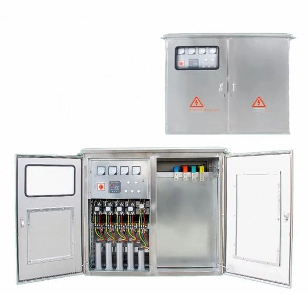
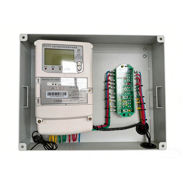
It connects to two independent power sources, enabling automatic switching to a secondary source during primary source failures. This seamless transition prevents disruptions to connected devices and enhances operational reliability. A dual power switching box is precisely the kind of gadget that guarantees a constant flow of electricity as it enables the user to shift the operational state between two different energy supplies. It can be found in homes, workplaces, factories, and anywhere else where sudden cuts of energy can. The ATS Dual Power Distribution Box plays a pivotal role in providing efficient low-voltage power solutions, ensuring that power flows seamlessly, even in the event of an outage. This comprehensive guide offers insights into the mechanisms and benefits of the ATS Dual Power Distribution Box. Transfer switches and sub panel boxes are key components in dual power switching cabinets. Transfer switches automatically switch between power sources during outages, ensuring uninterrupted power and system reliability. This redundancy ensures that if one power source fails, the other can immediately take over, minimizing downtime and preventing. A dual power switch helps you manage two power sources for one system. You can use it to keep your equipment working if the main power stops. This device quickly changes from the main supply to a backup source. This seamless transition.
[PDF]
M8 Mild steel fixings should be torqued to 28 NM (20. For reliable busbar connections, component selection matters—but torque control matters more. Best practices include: Yet even with perfect hardware, insufficient torque leads to high resistance. Proper busbar torque specification ensures enough compressive force to stabilize resistance over. Page 1 Medium-Voltage Switchgear Type 8DB10Extendable Fixed-Mounted Circuit-Breaker Switchgear up to 40. 5 kV Double Busbar, Single-pole Metal-Enclosed, Gas-Insulated Medium-Voltage Switchgear INSTALLATION AND OPERATING INSTRUCTIONS Order No. 9 Revision: 06 Issue: 26-02-2016. Failure to follow these instructions can result in injury or equipment damage. The elastic washers placed on the external sides of the connections and busbars help ensure for. At its core, busbar design must meet stringent industry standards, primarily addressing four key areas: thermal performance, mechanical strength, material selection, and electrical integrity. This comprehensive approach ensures that busbars operate stably under rated current conditions and can. Only install switchgear in closed rooms suitable for electrical equipment. Ensure that installation, operation and maintenance are carried out by specialist electricians only. Fully comply with the legally recognized standards (IEC or local), the connection conditions of the local electrical.
[PDF]

Rodent damage in underground or aerial installations. Symptoms: Gradual performance decline over months/years. UV exposure degrading jacket materials. Use Case: Identifying macrobends, breaks, or sharp bends in. In the high-stakes world of optical networking, even a minor disruption in a Pigtail Fiber connection can cascade into costly downtime, affecting data centers, telecom services, or industrial systems. This article equips engineers and network operators with actionable strategies to diagnose. Fiber pigtail failures can lead to unexpected signal loss, link instability, and repeated maintenance. Understanding how to identify early warning signs can help reduce downtime and protect your network from unnecessary failures. A visual check is often the first step when diagnosing a defective. However, when signal loss occurs in a 12 fiber pigtail, it can lead to disruptions in network performance, such as decreased data transfer speeds, increased error rates, or even complete outages. Understanding the potential causes of signal loss and implementing effective troubleshooting methods is. Executive Summary: A fiber optic pigtail is one of the most commonly specified yet least understood components in structured cabling. Dust or oil contamination leads to signal loss. Always clean fibers before splicing. Using the wrong connector (LC vs SC) can cause compatibility.
[PDF]
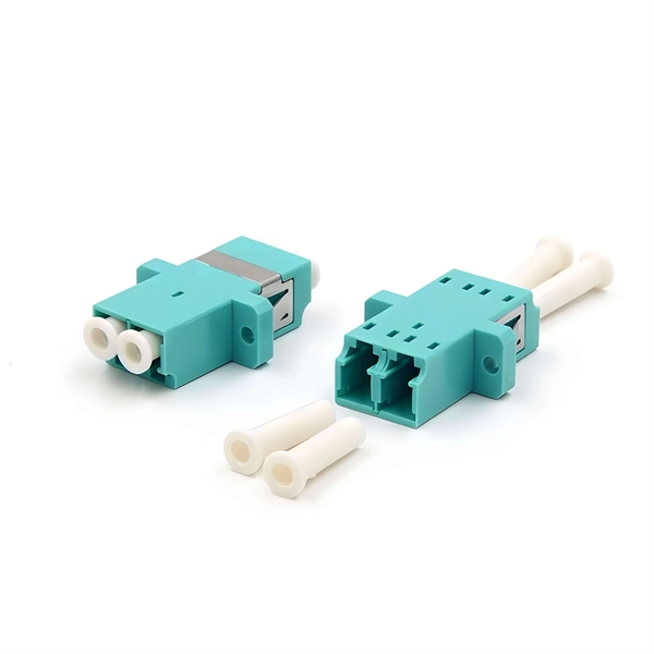
Pigtail, also known as pigtail, has only one end with a connector, and the other end is a broken end of a fiber optic cable core. It often appears in fiber optic terminal boxes. (couplers, jumpers, etc. are also used between. Long tail fibers consist of a phage-proximal and a phage-distal rod, each around 80 nm long and attached to each other at a slight angle. The phage-proximal rod is formed by a homo-trimer of gene product 34 (gp34) and is attached to the phage-distal rod by a monomer of gp35. are also used between them). One. The tailed phage T4 encodes a specialized device for this purpose, the long tail fiber (LTF), which allows the virus to move on the bacterial surface and find a suitable site for infection. Consequently, the infection efficiency of phage T4 is one of the highest, reaching the theoretical value of. Bacteriophages, often called phages, are viruses that infect and replicate within bacteria. These tiny biological entities play a significant role in microbial ecosystems. Tail fibers are structures on the phage that mediate their initial interaction with bacterial hosts, allowing them to recognize. The tail (Fig. Infection is initiated with the reversible attachment of six long tail fibers (LTFs) to the cell's outer layer of lipopolysaccharides, followed by transformation of the.
[PDF]