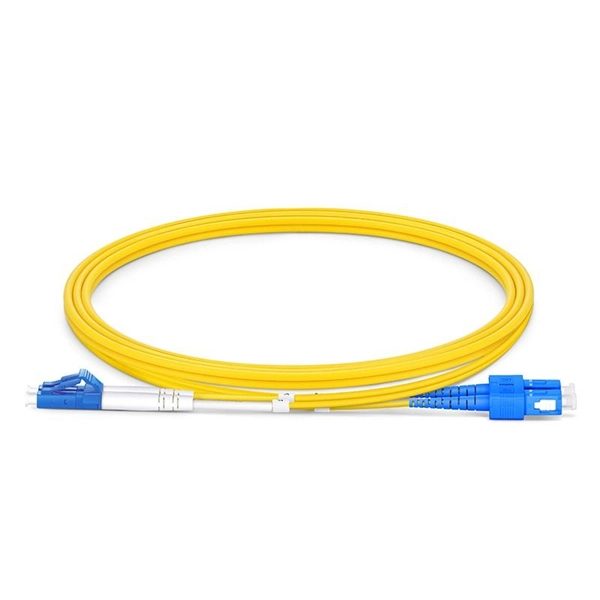
Its typical transmission distance is 20km or 40km. For instance, some ethernet switch manufacturers refer to the 1000BASE-LH SFP as the 1G 1310nm 40km SFP transceiver, which indicates the module's transmission distance and wavelength. The 10G SFP+ dual-fiber optical module is a small pluggable optical transceiver that adopts a dual-fiber bidirectional design. It completes signal transmission (Tx) and reception (Rx) through two independent optical fibers, ensuring the stability and reliability of signal transmission. An SFP (Small Form-factor Pluggable) module transmits data over fiber using specific wavelengths and power levels, which directly influence how far the signal can travel before degradation occurs. This is why two. If the optical module works at a wavelength near 850nm (880nm) or 910nm (940nm), then the module is a multi-mode fiber (MMF) optical transceiver, and if the working wavelength is 1310nm or 1550nm, it is a single-mode fiber (SMF)optical module. Generally, the maximum transmission distance(generally. The transmission distance of optical transceiver modules is divided into short distance, medium distance, and long distance. A 1-core module uses a single fiber core for data transmission, while a 2-core module uses two cores. o Think of a highway. Chromatic dispersion This is a key factor affecting single mode fiber distance.
[PDF]

Fiber optic cable can be run anywhere from 300 meters up to 80 kilometers (roughly 50 miles) depending on the cable type, transceiver used, and network standard. For most enterprise or data center applications using multimode fiber, the practical limit sits between 300 m and 550 m. Fiber optic cable transmission distance is determined by two primary physical factors that affect signal quality as light travels through the fiber medium. The greater the distance, the greater. Many factors decide the fiber cable distance, but the key factors include the below six aspects. Attenuation First is the attenuation of the optical fiber. OM2 extends this to 82 meters. OM1 fiber and OM2 fiber don't support these higher speeds. OM5 fiber matches OM4 at. For instance, without amplifiers, single-mode fiber can reach 50-60 miles and can support data rates of 1 Gbps or 10 Gbps. With amplifiers, such as Erbium-doped fiber amplifiers (EDFAs), the distance can be extended to 600 miles or more, and even further with additional amplifiers for long-haul.
[PDF]
A: Single mode fiber can typically transmit up to 160 km, and with dispersion compensation, it can exceed 200 km. Q: How far can multimode fiber go? A: The transmission distance of multimode fiber depends on the fiber type and data rate. However, for long-distance applications (e., metro and backbone networks), single mode fiber provides lower attenuation and future-proof scalability, resulting in lower long-term operational costs. For example, a fiber optic cable with a distance of 1km supports a bandwidth of 500MHz, while a fiber optic cable with a distance of 2km can only support a bandwidth of 250MHz. There are three main reasons for this: First, high-bandwidth. In the complex landscape of fiber optic infrastructure, selecting the right cable type—single-mode (OS1/OS2) or multimode (OM1/OM2/OM3/OM4/OM5)—can define a network's speed, reach, and cost-effectiveness. This guide dissects their technical nuances, evolution, and real-world applications. Fiber optic cable transmission distance is determined by two primary physical factors that affect signal quality as light travels through the fiber medium. Minimum Distance for Single-Mode Fiber: No Specific Limitation. Single-mode fiber is widely used in. Single-mode fiber (SMF): Uses a single light path, enabling it to transmit data over longer distances with less signal loss.
[PDF]
A power distribution box (also called PDU or distro) directs electricity from a main source to multiple circuits. It acts like a hub or traffic controller, managing power flow to different areas or devices. Today, electrical systems are essential for homes and industries. Knowing your distribution box helps you see which breaker does what. This makes fixing problems faster and keeps you safe. Good labeling of breakers is very important. Clear labels stop confusion. Key components include circuit breakers, fuses, bus bars, and internal wiring for safety and. Every home relies on a breaker box (also called a service panel or distribution board) to manage and protect its electrical circuits. Yet, one of the most overlooked steps in electrical safety and convenience is correctly labeling each circuit breaker. Too often, homeowners open their panel and. Distribution boards, often referred to as electrical panels or breaker boxes, serve as the nerve center of any electrical system. These essential components play a pivotal role in managing and distributing electrical power within a building or facility. In this comprehensive guide, we will explore. In descriptive statistics, a box plot or boxplot (also known as a box and whisker plot) is a type of chart often used in explanatory data analysis. Box plots visually show the distribution of numerical data and skewness by displaying the data quartiles (or percentiles) and averages. Box plots show.
[PDF]

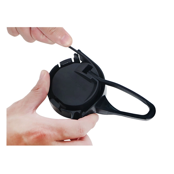
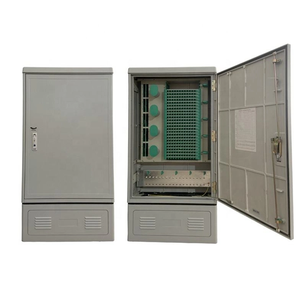
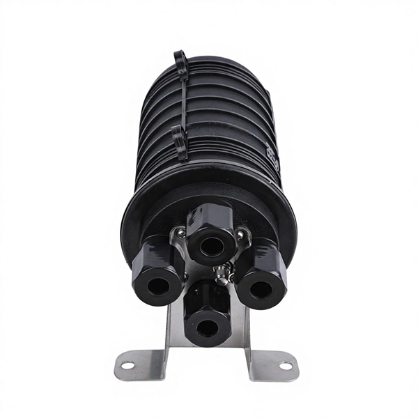
A typical fiber optic splice enclosure consists of several key components that work together to protect and organize the fiber splices. Standard enclosures contain: 1) Housing, 2) Cable fixation clamps, 3) Splice trays, 4) Sealing system. A splice box (also known as splice distributor) is a housing in which fiber optic cables begin or end. Fiber optics are fanned out in splice boxes that are situated at the end of fiber optic transmission paths. Optical cable joint box The optical cable joint box permanently connects two optical cables together and has a joint part for protecting components. The optical cable connection part, that is, the optical cable joint, is the part where the. An optical cable split fiber box, also known as a fiber distribution box or fiber optic splice closure, is a device used to terminate, splice, and distribute optical fibers. In this response, we will focus on the. This guide optimizes the original text by delving deeper into the three pillars of fiber network longevity: the impact of splicing technology, the strategic selection of splice boxes, and the essential maintenance protocols needed to ensure sustained, high-speed functionality. Fibre optic cables are manufactured in standardized lengths –.
[PDF]

It connects to two independent power sources, enabling automatic switching to a secondary source during primary source failures. This seamless transition prevents disruptions to connected devices and enhances operational reliability. A dual power switching box is precisely the kind of gadget that guarantees a constant flow of electricity as it enables the user to shift the operational state between two different energy supplies. It can be found in homes, workplaces, factories, and anywhere else where sudden cuts of energy can. The ATS Dual Power Distribution Box plays a pivotal role in providing efficient low-voltage power solutions, ensuring that power flows seamlessly, even in the event of an outage. This comprehensive guide offers insights into the mechanisms and benefits of the ATS Dual Power Distribution Box. Transfer switches and sub panel boxes are key components in dual power switching cabinets. Transfer switches automatically switch between power sources during outages, ensuring uninterrupted power and system reliability. This redundancy ensures that if one power source fails, the other can immediately take over, minimizing downtime and preventing. A dual power switch helps you manage two power sources for one system. You can use it to keep your equipment working if the main power stops. This device quickly changes from the main supply to a backup source. This seamless transition.
[PDF]

A protective relay is an intelligent electrical device designed to detect faults in power systems and initiate corrective actions such as tripping a circuit breaker. · Detection of the presence of a fault. · To close the trip circuit and operate the circuit breaker to isolate the faulty system from the healthier one. What is a protection relay? What is the purpose of protection. An electrically operated switch like a relay plays a key role in controlling an electrical circuit through an independent low-power signal, otherwise used where a number of circuits should be controlled through the single signal. Its main purpose is to safeguard electrical equipment like transformers, generators, and transmission lines from damage due to. A protection relay is a crucial component of electrical systems that safeguard infrastructure, employees, and equipment from electric problems and malfunctions. It functions as a watchdog by constantly surveying multiple system components including voltage, current, frequency, and phase angle. In other words, the prime function of protective relays is the timely and.
[PDF]
Cable laying services install fiber optic cable or copper cable in buildings and office complexes, or over large distances. They are staffed by cable technicians who perform cable preparation, jointing, termination, testing, commissioning, maintenance, and troubleshooting tasks. Installing fiber optic cables underground involves far more than digging trenches and placing cables. It forms a critical backbone for modern communication networks across both urban and rural environments. Project success depends on careful planning, precise installation practices, and proper. Installing underground fiber optic cables is critical to establishing high speed internet infrastructure that delivers reliable connectivity for businesses nationwide. Unlike traditional copper systems, fiber optic cables require specialized handling techniques and precise installation methods to. These skilled professionals ensure that your home or business is equipped with the latest fiber optic technology, providing blazing-fast Internet speeds and robust connections. This guide walks you through the entire process of fiber cable installation, from the initial assessment to the final. This involves burying or installing fiber-optic cables along predetermined routes. During this phase, locators identify existing utilities to prevent damage.
[PDF]

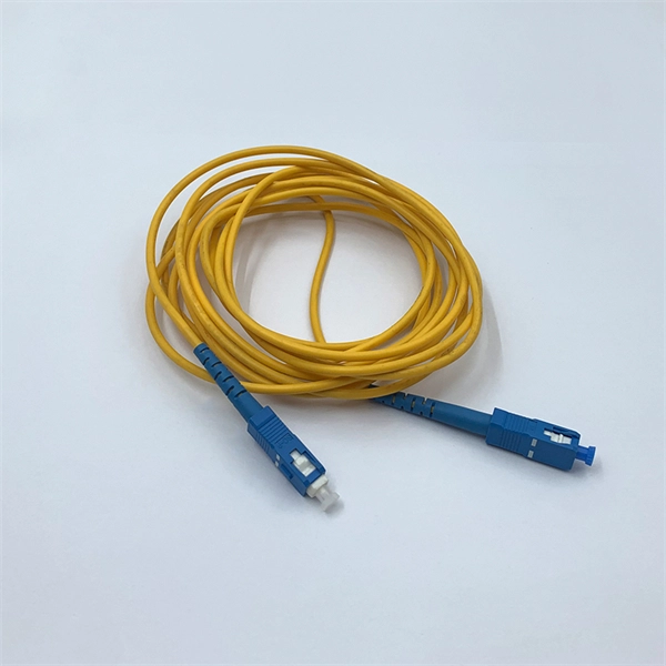
Since the earliest days of fiber optics, multimode cables have typically been color‑coded orange, black, or gray, while single‑mode cables are marked in yellow. For example, cable jacket color typically defines the fiber type, and can differ based on mode and performance level. These colors are typically chosen by industry standards bodies. However, there are some non-standardized colors and inconsistencies that you should be aware of. However, with the introduction of metallic connectors like FC and ST—whose bodies are difficult to color‑code—colored strain relief boots. Multimode fiber (MMF) is a kind of optical fiber mostly used in communication over short distances, for example, inside a building or for the campus. Multimode fiber optic cable has a larger core, typically 50 or 62. 5 microns that enables multiple light modes to be propagated. Because of this, more. Originally developed by the Electronic Industries Alliance (EIA) and the Telecommunications Industry Association (TIA), the TIA-598-D standard (formerly EIA/TIA-598) remains the most recognized color-coding system for optical fibers worldwide. On the right, the yellow patchcord indicates singlemode fiber and the blue connector means it is a regular PC polished connector, If it were an APC connector, it would be green. Perhaps nothing is.
[PDF]
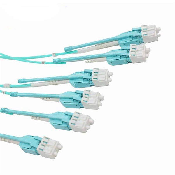
Fiber optic connectors can be categorized according to different standards such as utilization, fiber count, fiber mode, and transmission method. They are also divided into single-mode and multimode types based on their distinct characteristics. This guide will walk you through the most common fiber connector types, explaining their characteristics, advantages, and typical use cases. Whether you're planning an FTTH deployment, upgrading a data center, or working in telecom infrastructure, this guide will help you make informed decisions. Compared to Copper cables, Fiber connector types are incredibly varied. Where copper twisted pairs tend to terminate with an RJ45 plug, fiber optic connectors come in all sorts of shapes and sizes, with all manner of different use cases in mind. An optical fiber connector is used to join optical. With a wide variety of connector types available, choosing the right connector for your network can be challenging. Learn how each connector works, where it's used, and how to choose the right option for today's high-density, high-speed networks. It is a precise coupling device that joins fiber optic cables quickly, enabling faster connection and disconnection than splicing. The connector mechanically orients the fiber cores, allowing light to pass and travel through. In this guide, you'll explore various types of fiber optic cable connectors, each with unique features and best uses. We'll also provide practical advice.
[PDF]
This section provides an overview for server racks as well as their applications and principles. Are you choosing the right server rack manufacturer for your business? Whether you need racks, wall mounted network cabinets, or server cabinets, there are a variety of options available in the United States. Here are the top-ranked server rack companies as of April, 2026: 1. Cyber Power Systems USA. Some of the features include one-piece hinged covers, adjustable vented shelves, vertical cable management, floor mounting holes, integral front waterfall tops, pre-drilled holes, heavy gauge steel frames and vertical mounting-hole patterns. more+ Indoff is estimated to have 200-499 employees. At Rackmount Solutions, we provide rack, cabinet, and physical infrastructure systems designed with safety, protection and adaptability in mind. From open-frame racks to fully enclosed cabinets, our solutions keep equipment secure, organized, and ready for growth. We believe connectivity is the. Discover leading server cabinet manufacturers in the USA: Eabel, Hubbell, and others. Innovative, custom IT infrastructure solutions for diverse needs. They help to organize and secure important equipment by housing them. By selecting a reliable server cabinet manufacturer, you can make sure your equipment gets the best performance which is needed for data centers, networks and IT.
[PDF]
Networking cabinets are not automatically fire proof. A standard network cabinet is mainly designed for equipment installation, cable organization, ventilation, and routine physical protection, while a fire-resistant solution is built and tested for defined fire performance. Real fire protection. This IT server cabinet fireproof is the solution for highest fire and IT security requirements. As a complete, compact data center with all infrastructures such as air conditioning, UPS, monitoring, etc. Advantages: Nothing happens to your most. Fireproof server cabinets and other technologies like them are the new standard, and businesses are retrofitting existing configurations with newer server room fire suppression systems to minimize risk. Prevention these days saves a small fortune in the long term. This is one of the only ways a smoldering fire or. Rack mount fire protection solutions are designed for installation into server racks and server cabinets to provide fast and effective fire detection and suppression and reduce the threat of fire to business continuity. When sizing a rack mounted fire suppression unit it is important to measure the. The modular Smart Cage Room system allows the server room to be fully utilised in its available height. Accessories, UPS, air conditioning and cabling can be placed where they perform their function best. The use of space is therefore flexible. The open-ended height and free scalability support the.
[PDF]
Usually, the 10G/25G grey light optical modules with a short transmission distance are applied for connecting AAU/DU with WDM/OTN/SPN. The connections between WDM/OTN/SPN network devices can be achieved by 10G/25G/50G/100G dual-fiber or single-fiber bidirectional. Compared with Draft A (2013-07-30), this issue includes the following new topic: 2. This section describes engineering specifications of an AAU, including input power and equipment specifications. 7. In 2/3/4G networks, 10Gbps optical modules are generally enough for CPRI interfaces. In 5G networks, CPRI is also upgraded to eCPRI. Currently, 5G of the bearer network mainly uses 25Gbps optical modules. Next, ETU-LINK will introduce the types of optical modules used by 10G SFP+ and 25G SFP28. What is the difference between the 5G bearer network and the traditional optical transmission network? The main difference is that 5G fronthaul needs to support CPRI/eCPRI protocol. Most of the AAU of 5G base stations are deployed outdoors. In order to resist harsh environments such as high. The optical modules used to connect BBU and RRU devices are optical modules and optical fibers. Product Versions The following table lists the product versions related to this document. 25G SFP optical module adopts the wavelength of 850nm, with an operating.
[PDF]
Optical cable tray is a system designed to protect and route fiber optic patch cords, cable assemblies to and from network cabinets, ODF and other terminal devices. Ducting offers ideal solutions for optical raceway requirements and application with pleasing appearance and easy. Our Fiber Cable Tray System is a comprehensive raceway solution for data center, enterprise, central office, and mobile switching center applications. Designed to route and protect fiber optic and high-performance copper cabling to and from network cabinets, distribution frames, and other terminal. Cable trays are a foundational part of this infrastructure, offering a secure, scalable, and organized method of managing fiber routing across diverse environments.
[PDF]

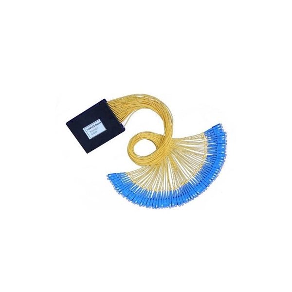
Fiber splitters serve as essential components in optical networks. These devices divide an optical signal from a single input into multiple outputs. This process enables efficient signal distribution across various network points. Fiber splitters function without the need for external. In the intricate web of modern fiber optic networks, where data travels at the speed of light across continents, fiber optic splitters play a silent yet pivotal role. These unassuming devices enable a single optical signal to be divided into multiple paths, making them indispensable for sharing. A fiber splitter, also known as a beam splitter, is a passive optical device that splits an optical signal into multiple signals. By dividing a single optical signal into multiple signals, fiber. Fiber optic splitters are vital in modern communication networks. Fiber optic splitters, such as plcsplitter and fbt splitters, are crucial in maintaining signal integrity, with considerations for IL (Insertion Loss) and RL (Return Loss). They are integral components in the world of telecommunication and data networking, crucial to maintaining reliable and efficient communication infrastructures. There are two primary.
[PDF]