A protective relay is an intelligent electrical device designed to detect faults in power systems and initiate corrective actions such as tripping a circuit breaker. · Detection of the presence of a fault. · To close the trip circuit and operate the circuit breaker to isolate the faulty system from the healthier one. What is a protection relay? What is the purpose of protection. An electrically operated switch like a relay plays a key role in controlling an electrical circuit through an independent low-power signal, otherwise used where a number of circuits should be controlled through the single signal. Its main purpose is to safeguard electrical equipment like transformers, generators, and transmission lines from damage due to. A protection relay is a crucial component of electrical systems that safeguard infrastructure, employees, and equipment from electric problems and malfunctions. It functions as a watchdog by constantly surveying multiple system components including voltage, current, frequency, and phase angle. In other words, the prime function of protective relays is the timely and.
[PDF]
A junction box contains two trade size 3 raceways on the left side and one trade size 3 raceway on the right side. raceway on the right side, and one 3-in. raceways on. Pull boxes, junction boxes, and conduit bodies must be sized to allow conductors 4 AWG and larger to be installed without damage to the conductor insulation. The NEC provides sizing requirements in 314. Keep in mind these requirements address conductors used for general wiring, such as those. Article 370 covers the installation and use of all boxes (and conduit bodies) used as outlet, junction, or pull boxes, depending on their use. You're reading an older article from ELECTRICAL CONTRACTOR. Some content, such as code-related information, may be outdated. Visit our homepage to view the. When conductors enter an enclosure with a removable cover, such as a conduit body or wireway, the minimum distance from the raceway entry to the removable cover is the bending distance listed in Table 312. 6 (A) for one conductor per terminal [314. This approach helps in the safe organization of wires. To stop a fire from beginning or spreading, sparks are contained by fireproof connections and boxes. In this reading, we will delve into the definition of a. For example, a box is needed for eight 2-inch conduits. Each conduit will contain 2/0 conductors that will be spliced within the box. What is the minimum length required for the left/right (“X”) dimension? The minimum distance required because of the.
[PDF]
A fiber array (FA) is an arrangement where a bundle of optical fibers or a fiber ribbon is mounted onto a substrate with predefined spacing, typically using a V-groove baseplate. In optical communications, a fiber array mainly consists of a baseplate, a pressure plate, and optical. Fiber Arrays (FAs) are foundational components that enable this alignment by organizing multiple optical fibers into a compact and highly accurate format. Whether integrated into planar lightwave circuits (PLCs), optical switches, or high-speed transceivers, FAs play a vital role in ensuring. What is a Fiber Array (FA)? A Fiber Array, commonly abbreviated as FA, is a critical interface component in Silicon Photonics (SiPh) packaging, Photonic Integrated Circuits (PIC), and Co-Packaged Optics (CPO) architectures. It is responsible for efficiently coupling "external optical fibers" with. Fiber arrays, also known as fiber-optic arrays or fiber array units, are crucial components in the field of photonics. These arrays can be one-dimensional or two-dimensional, consisting of optical fibers that are often arranged at the end of a fiber bundle. What is a Fiber Array? A fiber array is an optical device that aligns and secures a bundle of. and data center applications. Often, such an array is formed only for the very end of a bundle of fibers, rather than over the whole fiber length. The purpose of such an array is typically either coupling light from.
[PDF]

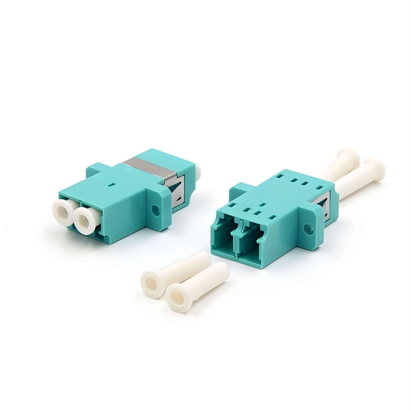
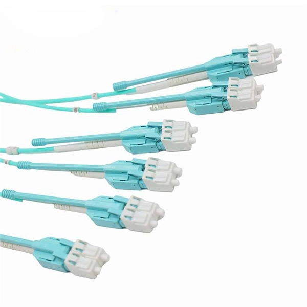
Multi-mode fiber optic patch cords utilize a larger core size, typically around 50-100 microns, allowing them to carry multiple modes of light. This design enables the transmission of data over relatively short distances with high bandwidth capabilities. A fiber-optic patch cord is a fiber-optic cable capped at each end with connectors that allow it to be rapidly and conveniently connected to telecommunication equipment. This is known as interconnect-style cabling. A fiber-optic patch cord is constructed from a core with a high refractive. These short fiber optic cords connect transceivers, switches, patch panels, and servers. Without them, even the best optical modules and switches cannot deliver performance. As data rates increase from 10G → 100G → 400G → 800G, patch cables must handle more bandwidth, more density, and stricter. Fiber optic patch cords, also known as fiber optic patch cables or fiber jumpers, are indispensable components in modern optical networks. They act as the critical link for interconnecting devices like optical switches, servers, and distribution frames. Understanding the various technical. Fiber patch cables, also called fiber-optic patch cords, are cables typically containing one or two optical fibers, which are equipped with standardized fiber connectors on both ends. The function of the fiber patch cord.
[PDF]
Usually, the 10G/25G grey light optical modules with a short transmission distance are applied for connecting AAU/DU with WDM/OTN/SPN. The connections between WDM/OTN/SPN network devices can be achieved by 10G/25G/50G/100G dual-fiber or single-fiber bidirectional. Compared with Draft A (2013-07-30), this issue includes the following new topic: 2. This section describes engineering specifications of an AAU, including input power and equipment specifications. 7. In 2/3/4G networks, 10Gbps optical modules are generally enough for CPRI interfaces. In 5G networks, CPRI is also upgraded to eCPRI. Currently, 5G of the bearer network mainly uses 25Gbps optical modules. Next, ETU-LINK will introduce the types of optical modules used by 10G SFP+ and 25G SFP28. What is the difference between the 5G bearer network and the traditional optical transmission network? The main difference is that 5G fronthaul needs to support CPRI/eCPRI protocol. Most of the AAU of 5G base stations are deployed outdoors. In order to resist harsh environments such as high. The optical modules used to connect BBU and RRU devices are optical modules and optical fibers. Product Versions The following table lists the product versions related to this document. 25G SFP optical module adopts the wavelength of 850nm, with an operating.
[PDF]
Picking up the best router for fiber internet isn't just about going to the market and choosing one of the best wireless routers. Instead, you need to carefully look at its specs, performance, and the type of securit.
[PDF]
What Is an Explosion Proof Junction Box? An explosion proof junction box is a sealed electrical enclosure designed to contain sparks or flames that may occur within the box, preventing them from igniting explosive gases or dust in the surrounding environment. Explosion-proof electrical distribution boxes are essential for safety in hazardous environments. These specialized enclosures are built to contain internal explosions and stop the ignition of flammable materials. In this article, we will explore three key aspects:. Explosion-proof enclosures are used by such facilities to ensure the safe housing of electrical components that could cause a spark and ignite these gases in the atmosphere. What Is An Explosion Proof Box or Enclosure? They are a cast aluminum or iron box that can withstand a heavy-duty explosion. Specification code(I,II,IIB. Flameproof enclosure (Ex d IIB+H2), which can be used as feed distribution equipment in control and distribution system (such as distribution box, switch box of main circuit, control box, terminal box or motor starting box etc. ) ·Enclosure: stainless steel. Equipped. (a) A cable passing through an outside wall (s) of a distribution box shall be conducted either through a packing gland or an interlocked plug and receptacle. (b) Short-circuit protection shall be provided for each branch circuit connected to a distribution box. The current-carrying capacity of the.
[PDF]
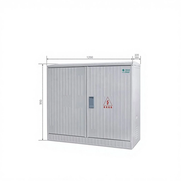
A power distribution box (also called PDU or distro) directs electricity from a main source to multiple circuits. It acts like a hub or traffic controller, managing power flow to different areas or devices. Today, electrical systems are essential for homes and industries. Knowing your distribution box helps you see which breaker does what. This makes fixing problems faster and keeps you safe. Good labeling of breakers is very important. Clear labels stop confusion. Key components include circuit breakers, fuses, bus bars, and internal wiring for safety and. Every home relies on a breaker box (also called a service panel or distribution board) to manage and protect its electrical circuits. Yet, one of the most overlooked steps in electrical safety and convenience is correctly labeling each circuit breaker. Too often, homeowners open their panel and. Distribution boards, often referred to as electrical panels or breaker boxes, serve as the nerve center of any electrical system. These essential components play a pivotal role in managing and distributing electrical power within a building or facility. In this comprehensive guide, we will explore. In descriptive statistics, a box plot or boxplot (also known as a box and whisker plot) is a type of chart often used in explanatory data analysis. Box plots visually show the distribution of numerical data and skewness by displaying the data quartiles (or percentiles) and averages. Box plots show.
[PDF]

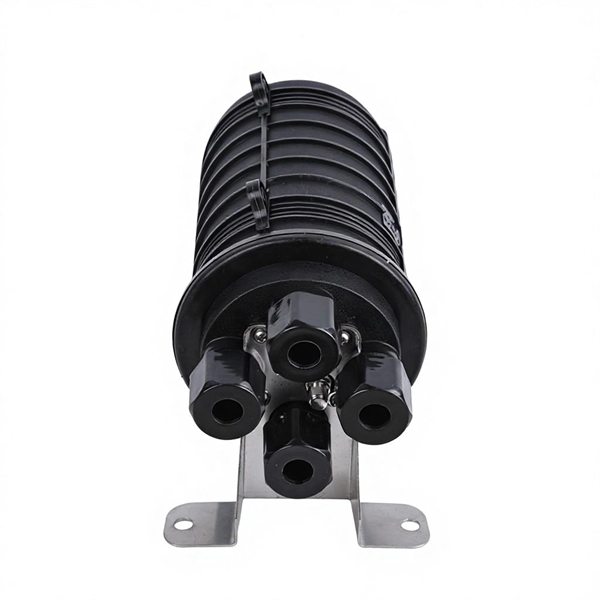
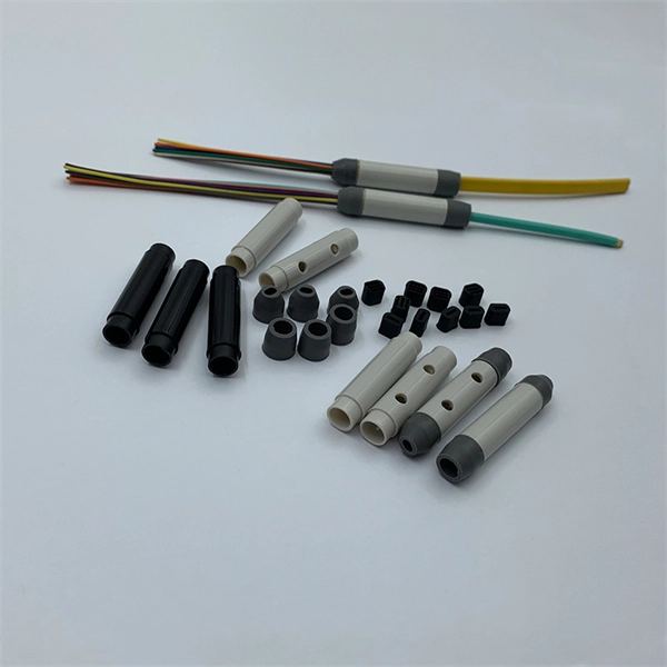
A typical fiber optic splice enclosure consists of several key components that work together to protect and organize the fiber splices. Standard enclosures contain: 1) Housing, 2) Cable fixation clamps, 3) Splice trays, 4) Sealing system. A splice box (also known as splice distributor) is a housing in which fiber optic cables begin or end. Fiber optics are fanned out in splice boxes that are situated at the end of fiber optic transmission paths. Optical cable joint box The optical cable joint box permanently connects two optical cables together and has a joint part for protecting components. The optical cable connection part, that is, the optical cable joint, is the part where the. An optical cable split fiber box, also known as a fiber distribution box or fiber optic splice closure, is a device used to terminate, splice, and distribute optical fibers. In this response, we will focus on the. This guide optimizes the original text by delving deeper into the three pillars of fiber network longevity: the impact of splicing technology, the strategic selection of splice boxes, and the essential maintenance protocols needed to ensure sustained, high-speed functionality. Fibre optic cables are manufactured in standardized lengths –.
[PDF]

It connects to two independent power sources, enabling automatic switching to a secondary source during primary source failures. This seamless transition prevents disruptions to connected devices and enhances operational reliability. A dual power switching box is precisely the kind of gadget that guarantees a constant flow of electricity as it enables the user to shift the operational state between two different energy supplies. It can be found in homes, workplaces, factories, and anywhere else where sudden cuts of energy can. The ATS Dual Power Distribution Box plays a pivotal role in providing efficient low-voltage power solutions, ensuring that power flows seamlessly, even in the event of an outage. This comprehensive guide offers insights into the mechanisms and benefits of the ATS Dual Power Distribution Box. Transfer switches and sub panel boxes are key components in dual power switching cabinets. Transfer switches automatically switch between power sources during outages, ensuring uninterrupted power and system reliability. This redundancy ensures that if one power source fails, the other can immediately take over, minimizing downtime and preventing. A dual power switch helps you manage two power sources for one system. You can use it to keep your equipment working if the main power stops. This device quickly changes from the main supply to a backup source. This seamless transition.
[PDF]
Optical fibers can be used as sensors to measure, , and other quantities by modifying a fiber so that the quantity to be measured modulates the,,, or transit time of light in the fiber. Sensors that vary the intensity of light are the simplest, since only a simple source and detector are required. A particularly useful feature of intrinsic fiber-optic sensors is that they can, if required, provide distributed sensing over very large distances.
[PDF]

The terminal box provides: Strain relief: Cable clamps and grommets transfer tensile loads from fiber to chassis, preventing microbends and fiber breakage. Bend-radius control: Internal routing with ≥30 mm radius (typical for G. A2/B3 bend-insensitive fibers) minimizes induced attenuation. Slack. A Fiber Access Terminal (FAT), also known as a Fiber Access Terminal Box (ATB) or Fiber Distribution Terminal (FDT), is a key component found in optimized fiber optic access networks for FTTH implementations. It is a small enclosure that can house and protect the fiber optic cables, splices, and connectors. The fiber termination box. GAO Tek's fiber terminal boxes are devices used in fiber optic networks to terminate and manage fiber optic cables. Our boxes serve as a connection point for incoming and outgoing cables, providing cable termination, organization, and protection. GAO's box includes features such as cable. Fiber optic terminal box is a product use for different scenarios in FTTH construction, such as primary or secondary splitting. People usually use it to connect patch cables from the splitter to the indoor cables, meeting the demands for high-speed bandwidth services. It is widely used in optical fiber communication systems, such as Fiber to the Home (FTTH), Local.
[PDF]
Multimode Fiber Optic Receivers are devices designed to interpret information contained in optical signals transmitted through multimode fibers. These receivers convert the optical signals into electrical signals, allowing the data to be processed and utilized by electronic systems. Multimode Fiber. They convert electrical signals into optical signals for transmission over fiber-optic cables and reverse the process at the receiving end. Now, the term 'multimode' stems from the fact that these transceivers use multimode fiber (MMF) cables, which can carry multiple beams of light — or 'modes' —. Multi-mode optical fiber is a type of optical fiber mostly used for communication over short distances, such as within a building or on a campus. Multi-mode links can be used for data rates up to 800 Gbit/s. Most systems operate by transmitting in one direction on one fiber and in the reverse direction on another fiber for full duplex operation. For applications where long-haul transmission is unnecessary, multimode SFP modules offer a practical. They have a wider core (around 50 to 62. 5 micrometers), which enables multiple modes or light paths to coexist within the fiber, thus resulting in modal dispersion at shorter distances but reducing its efficacy over longer stretches. The choice between Single-Mode Fiber (SMF) and Multimode Fiber.
[PDF]
In practical applications, there are many electrical connection methods for industrial power distribution boxes, which will be introduced below. Primary distribution systems consist of feeders that deliver power from distribution substations to distribution transformers. Many feeders leave substation in a concrete ducts and are routed to a nearby pole. At this. Proper sub panel wiring is a fundamental skill for any licensed electrician, critical for safely expanding a building's electrical capacity. The process involves installing a secondary breaker panel fed from the main service panel. Key compliance points include performing an accurate panelboard. Four basic circuit arrangements are used for the distribution of electric power: radial, primary selective, secondary selective, and secondary network circuit arrangements. A busbar is a large-section conductive. The Secondary Distribution Box (SDB) receives power from Main Power Distribution box via an extender cable and provides a central power distribution to feed normal branch circuits to the electric floor modules through snap-on extender cables. The SDB can be fitted with terminal blocks for custom. Small electrical installations normally have only one distribution board, connected directly to the main service, and appliances are powered with branch circuits protected by breakers. However, powering all loads from the same distribution board is impractical in larger installations, since the.
[PDF]
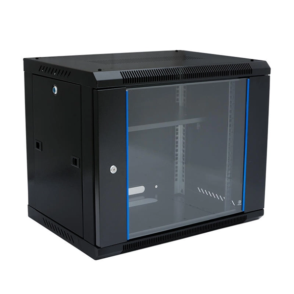
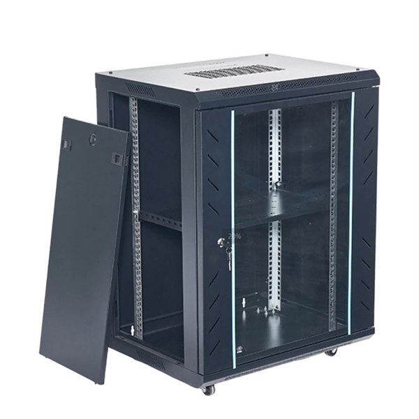
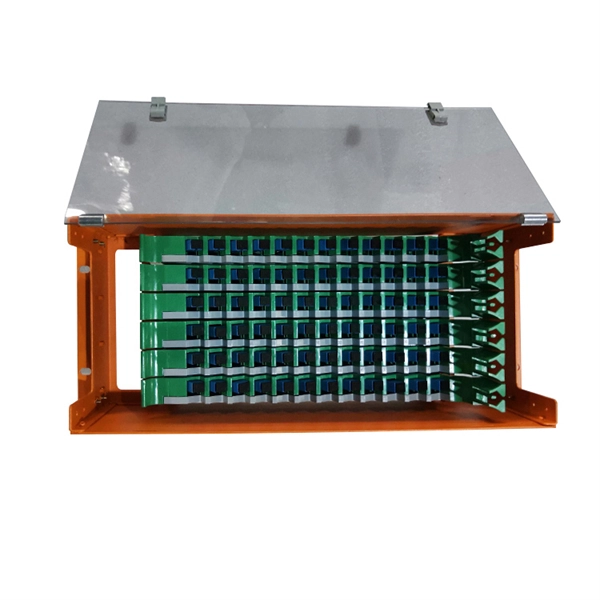
An Optical Distribution Frame (ODF) is a dedicated unit designed to organize, terminate, and interconnect fiber optic cables. It brings together fiber splicing, patching, and cable routing in a single structure, while shielding sensitive connectors and splices from mechanical. In the complex architecture of fiber optic networks, the Optical Distribution Frame (ODF) serves as the linchpin for organizing, protecting, and distributing optical signals. Whether in data centers, telecom central offices, or enterprise network rooms, ODFs enable efficient fiber management. Among the many solutions available, the Optical Distribution Frame (ODF) plays a central role in organizing, protecting, and simplifying fiber management in telecom rooms, central offices, and data centers. As data centers, enterprises, telecom operators, and smart-building infrastructures deploy increasingly dense fiber links, ODFs provide the structured. Optical Distribution Frames (ODF) are indispensable components in optical communications networks. They provide efficient fiber optic management, connectivity, and protection. Whether you are building a data center, deploying FTTx networks, or managing the telecom systems, the selection of suitable ODF is very important since the fiber connections are optimized.
[PDF]