M8 Mild steel fixings should be torqued to 28 NM (20. For reliable busbar connections, component selection matters—but torque control matters more. Best practices include: Yet even with perfect hardware, insufficient torque leads to high resistance. Proper busbar torque specification ensures enough compressive force to stabilize resistance over. Page 1 Medium-Voltage Switchgear Type 8DB10Extendable Fixed-Mounted Circuit-Breaker Switchgear up to 40. 5 kV Double Busbar, Single-pole Metal-Enclosed, Gas-Insulated Medium-Voltage Switchgear INSTALLATION AND OPERATING INSTRUCTIONS Order No. 9 Revision: 06 Issue: 26-02-2016. Failure to follow these instructions can result in injury or equipment damage. The elastic washers placed on the external sides of the connections and busbars help ensure for. At its core, busbar design must meet stringent industry standards, primarily addressing four key areas: thermal performance, mechanical strength, material selection, and electrical integrity. This comprehensive approach ensures that busbars operate stably under rated current conditions and can. Only install switchgear in closed rooms suitable for electrical equipment. Ensure that installation, operation and maintenance are carried out by specialist electricians only. Fully comply with the legally recognized standards (IEC or local), the connection conditions of the local electrical.
[PDF]
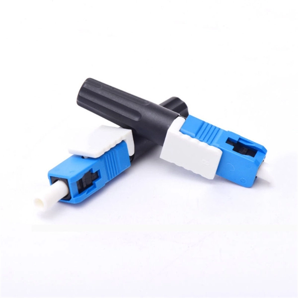
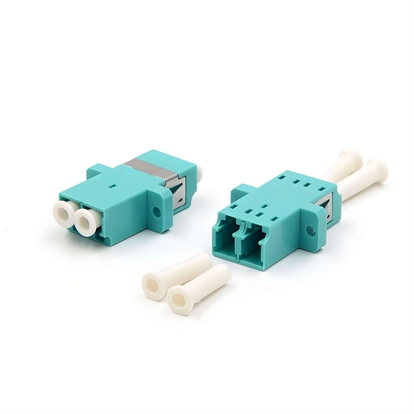
The bare fiber end is designed to be fusion spliced or mechanically spliced to the fiber optic cable in the field. This design makes pigtails the ideal choice for applications where fibers from a large cable must be terminated at an ODF (Optical Distribution Frame), terminal box, or. By combining factory-installed connectors with spliced bare fiber, pigtails ensure that network installers can create fast, reliable, and cost-effective terminations. Without pigtails, every termination in an ODF, terminal box, or splice closure would require field-installed connectors—an approach. ■ What is a fiber optic pigtail cable? A pigtail fiber indicates a short length of optical fiber cable that has a pigtail connector (for example, SC, FC, ST, LC, etc. This. A fiber pigtail is typically a fiber optic cable with one end factory pre-terminated fiber connector and the other exposed fiber. It is usually suitable for field termination using a mechanical or fusion splicer. Its primary function is to connect active network devices (e., switches, routers, transceivers) to passive components (e., patch panels, ODFs) or other devices. Think of it as a.
[PDF]
🏃♂️�� Grenada Intercol 2023 – Boys Open 4x400m Relay Watch the thrilling relay action from the 2023 Republic Bank Inter‑Secondary Schools Athletic Championships (INTERCOL) held at the Kirani James Athletics Stadium in St. more 🏃♂️🔥 Grenada Intercol 2023 – Boys Open 4x400m Relay. Our Relay Services provides the full range of services such as: TTY, Voice Carry Over (VCO), two-line Voice Carry Over (2LVCO), Hearing Carry Over (HCO), Speech-to-Speech (STS), Visually Assisted Speech-to-Speech (VA STS), ASCII, Voice, Enhanced Voice Carryover (Captioned Telephone or CapTel), and. No description has been added to this video. Audio tracks for some languages were automatically generated. Learn more Enjoy the videos and music you love, upload original content, and share it all with friends, family, and the world on YouTube. CARIFTA GAMES GRENADA 2026 | GIRLS 4x400M RELAY U17 FINAL | DAY 3 Until This Happened 😱 No description has been added to this video.
[PDF]
A fiber-optic sensor is a sensor that uses optical fiber either as the sensing element ("intrinsic sensors"), or as a means of relaying signals from a remote sensor to the electronics that process the signals ("extrinsic sensors"). Fibers have many uses in remote sensing. Depending on the application, fiber may be used because of its small size, or because no electrical power is needed at th. Intrinsic sensorsOptical fibers can be used as sensors to measure, , and other quantities by modifying a fiber so that the quantity to be measured modulates the,,, or transit time. Extrinsic fiber-optic sensors use an, normally a one, to transmit light from either a non-fiber optical sensor, or an electronic sensor connected to an optical transmitter. A major benefit of e. It is well-known the propagation of light in optical fiber is confined in the core of the fiber based on the total internal reflection (TIR) principle and near-zero propagation loss within the cladding, which is very important f.
[PDF]

A protective relay is an intelligent electrical device designed to detect faults in power systems and initiate corrective actions such as tripping a circuit breaker. · Detection of the presence of a fault. · To close the trip circuit and operate the circuit breaker to isolate the faulty system from the healthier one. What is a protection relay? What is the purpose of protection. An electrically operated switch like a relay plays a key role in controlling an electrical circuit through an independent low-power signal, otherwise used where a number of circuits should be controlled through the single signal. Its main purpose is to safeguard electrical equipment like transformers, generators, and transmission lines from damage due to. A protection relay is a crucial component of electrical systems that safeguard infrastructure, employees, and equipment from electric problems and malfunctions. It functions as a watchdog by constantly surveying multiple system components including voltage, current, frequency, and phase angle. In other words, the prime function of protective relays is the timely and.
[PDF]
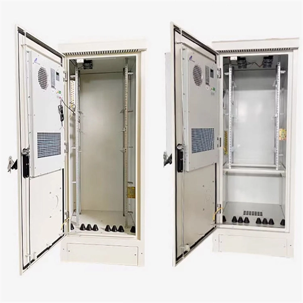
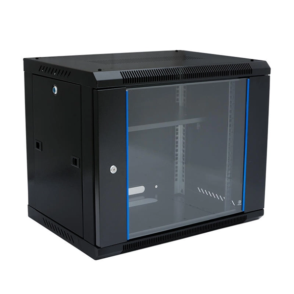
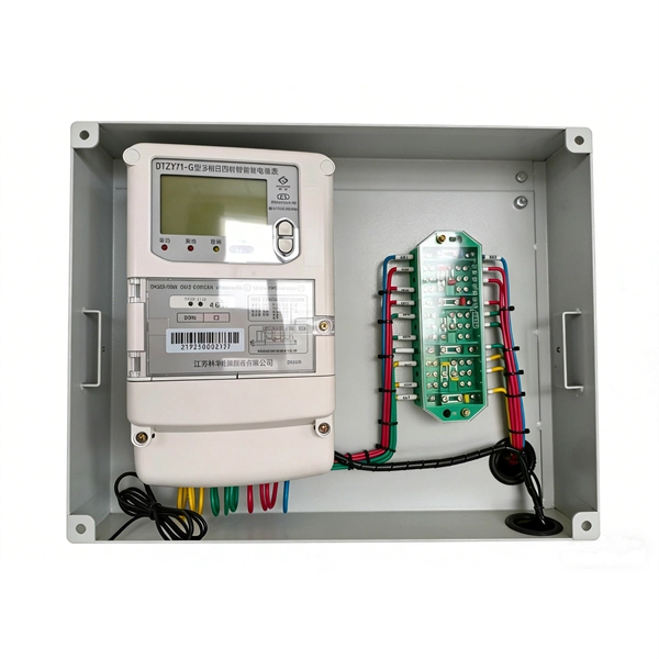
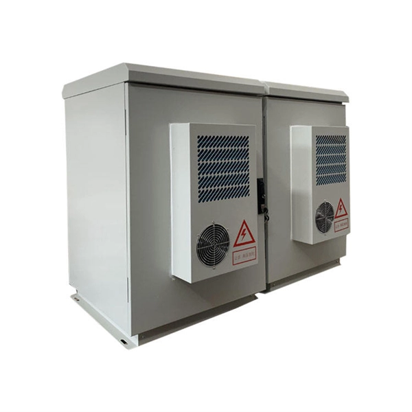
A power distribution box (also called PDU or distro) directs electricity from a main source to multiple circuits. It acts like a hub or traffic controller, managing power flow to different areas or devices. Today, electrical systems are essential for homes and industries. Knowing your distribution box helps you see which breaker does what. This makes fixing problems faster and keeps you safe. Good labeling of breakers is very important. Clear labels stop confusion. Key components include circuit breakers, fuses, bus bars, and internal wiring for safety and. Every home relies on a breaker box (also called a service panel or distribution board) to manage and protect its electrical circuits. Yet, one of the most overlooked steps in electrical safety and convenience is correctly labeling each circuit breaker. Too often, homeowners open their panel and. Distribution boards, often referred to as electrical panels or breaker boxes, serve as the nerve center of any electrical system. These essential components play a pivotal role in managing and distributing electrical power within a building or facility. In this comprehensive guide, we will explore. In descriptive statistics, a box plot or boxplot (also known as a box and whisker plot) is a type of chart often used in explanatory data analysis. Box plots visually show the distribution of numerical data and skewness by displaying the data quartiles (or percentiles) and averages. Box plots show.
[PDF]
Picking up the best router for fiber internet isn't just about going to the market and choosing one of the best wireless routers. Instead, you need to carefully look at its specs, performance, and the type of securit.
[PDF]
CMP CXT type brass indoor and outdoor cable gland for use with all types of screened flexible wire braid (e. CY/SY), or wire braid armour cable. The cable gland provides an environmental seal on the cable outer sheath. Want to discuss this product with one of the CMP Technical Team? Call one of our team now on +44 191 265 7411 We have some exciting things in the pipeline - if you'd like to be the first to know please enter your email address below. Note: Supplied with Locknut & Washer. In summary, CXT is an abbreviation that can stand for various terms depending on the context, and its interpretation can vary across different fields such as technology, business, education, geography, government, law and other specialized areas. Features: Kit Contents: Additional Accessories available (upon request): The information in this datasheet is for. Operating Temp. Entry thread protection rating:. CMP CX Single seal brass cable gland suitable for braided, pliable wire and steel tape armoured cables. Our state-of-the-art cable testing facility ensures that every cable meets the highest standards of quality and compliance through continuous, rigorous testing. Where applicable, cables are.
[PDF]

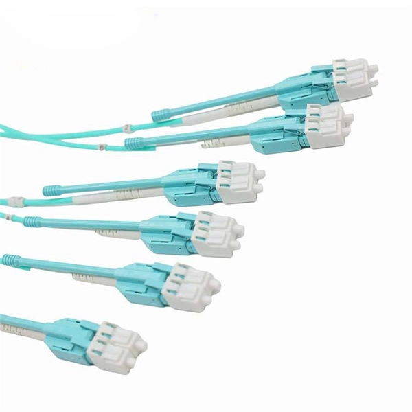
Even when a network is designed correctly, real-world conditions—fiber handling, connector cleanliness, splices, environmental stress, and aging—can gradually increase attenuation or introduce reflections and interference. Fiber optic patch cords are often treated as low-risk consumables, yet a large percentage of optical link failures originate at the patch cord level. Unlike backbone cables, patch cords are frequently connected, disconnected, bent, and handled by technicians, making them the most vulnerable. Optical attenuation is the gradual loss of flux (light intensity) as an optical signal travels through a fiber. Measured in decibels (dB), it's the logarithmic ratio of the output power to the input power. Every network has a "loss budget". Field guide for diagnosing high fiber optic attenuation. Learn to use the OTDR to identify contamination, micro-bends, and poor splices, ensuring your 400G network links remain within budget. This article explains practical, engineering-focused ways to mitigate signal. This measurement helps determine the efficiency of a fiber optic system. Several factors contribute to signal attenuation. These include absorption, scattering, and bending losses. Each factor plays a significant role in the overall performance of a network. Whether you're a network engineer, IT manager, or service provider, understanding these challenges and how to address them is critical for maintaining high-performance, reliable.
[PDF]
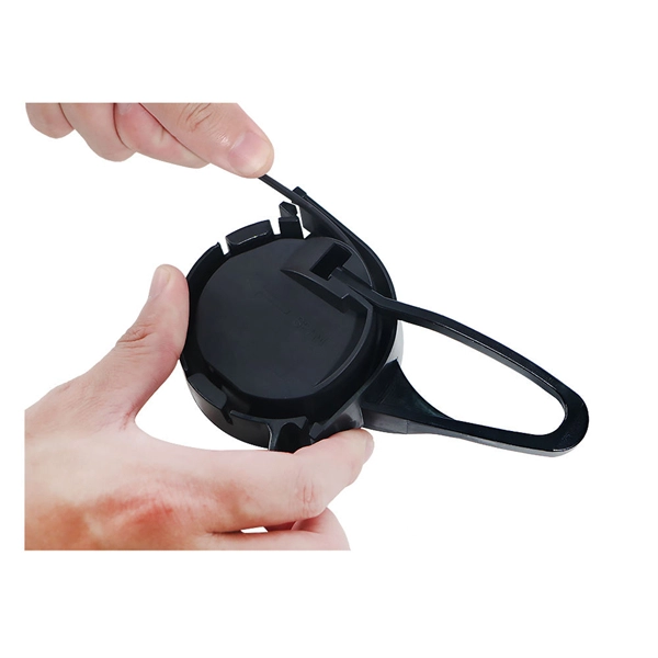
A junction box contains two trade size 3 raceways on the left side and one trade size 3 raceway on the right side. raceway on the right side, and one 3-in. raceways on. Pull boxes, junction boxes, and conduit bodies must be sized to allow conductors 4 AWG and larger to be installed without damage to the conductor insulation. The NEC provides sizing requirements in 314. Keep in mind these requirements address conductors used for general wiring, such as those. Article 370 covers the installation and use of all boxes (and conduit bodies) used as outlet, junction, or pull boxes, depending on their use. You're reading an older article from ELECTRICAL CONTRACTOR. Some content, such as code-related information, may be outdated. Visit our homepage to view the. When conductors enter an enclosure with a removable cover, such as a conduit body or wireway, the minimum distance from the raceway entry to the removable cover is the bending distance listed in Table 312. 6 (A) for one conductor per terminal [314. This approach helps in the safe organization of wires. To stop a fire from beginning or spreading, sparks are contained by fireproof connections and boxes. In this reading, we will delve into the definition of a. For example, a box is needed for eight 2-inch conduits. Each conduit will contain 2/0 conductors that will be spliced within the box. What is the minimum length required for the left/right (“X”) dimension? The minimum distance required because of the.
[PDF]
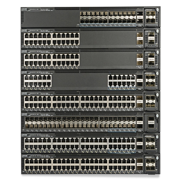
It can be seen from the above that the aggregation switch has functions such as source address, destination address filtering, real-time policy, security, network isolation, and segmentation. Compared with access switches, aggregation switches have better performance and higher. What is an Aggregation Switch and How Does it Work? An aggregation switch consolidates data traffic from multiple network access switches into a single high-bandwidth link directed toward a core network or data center. The primary function of an aggregation switch is to aggregate and forward data. A fiber optic aggregation switch is a high-capacity network device designed to integrate and manage multiple fiber optic connections from access layer switches into fewer and faster uplink connections to the core network. It is essential for larger networks requiring efficient data flow. You may also. All-optical Ethernet switches are a type of switch that provides optical uplink and downlink ports, making them an ideal choice for building an all-optical campus network. They can function as core, aggregation, and access devices on campus networks and connect to upstream and downstream devices. As the physical entity of the aggregation layer, the aggregation switch's primary function is to aggregate the data of the access layer switch and forward it to the core switch to reduce the burden on the core layer. Cisco's aggregation switch What is the Role of the Aggregation Switch in the.
[PDF]

The wavelength of the 40G QSFP+ SR4 optical module is 4x850nm, while the 40G QSFP+ LR4 optical module adopts CWDM coarse wavelength division multiplexing technology, with four wavelengths of 1271nm, 1291nm, 1311nm, and 1331nm. The fiber type and connector are different. 40GBASE-ER4 is a long-reach 40GbE optical standard that delivers 40Gbps transmission over single-mode fiber up to 40km using QSFP+ transceiver. It achieves this reach by multiplexing four CWDM optical lanes into a duplex LC fiber interface, allowing long-distance connectivity without requiring. While 100G and 400G technologies continue to advance, 40G QSFP+ optical modules remain a mainstream, cost-effective solution for upgrading small to medium-sized data centers. It is commonly deployed in data centers, enterprise backbone networks, and metropolitan area networks where stable, high-speed transmission over extended distances is. In the deployment of 40G networks, the 40G QSFP+ optical module is one of the most widely used, defined by IEEE 802. The two basic interface specifications for QSFP+ optical modules are 40G BASE-SR4 and 40G BASE-LR4. In this blog, ETU-LINK will talk about. The QSFP+ module is designed for use in 40GBASE Ethernet throughput up to 10km, 30km or 40km over single mode fiber (SMF) using a wavelength of 1310nm via duplex LC connectors. This transceiver is compliant with QSFP+ MSA and IEEE 802. Digital diagnostics functions are also available.
[PDF]
Optical cable tray is a system designed to protect and route fiber optic patch cords, cable assemblies to and from network cabinets, ODF and other terminal devices. Ducting offers ideal solutions for optical raceway requirements and application with pleasing appearance and easy. Our Fiber Cable Tray System is a comprehensive raceway solution for data center, enterprise, central office, and mobile switching center applications. Designed to route and protect fiber optic and high-performance copper cabling to and from network cabinets, distribution frames, and other terminal. Cable trays are a foundational part of this infrastructure, offering a secure, scalable, and organized method of managing fiber routing across diverse environments.
[PDF]
While fiberglass cable tray systems utilize a heat-cured resin that doesn't melt at higher temperatures, it's important to realize there is a slight loss of rigidity at continuously elevated temperatures. Your assurance as an engineer should be based on evidence, specifically the Air Thermal Aging Test Report. You don't need to be a materials expert. You need to know how to evaluate three. A fiberglass cable tray is a vital component in modern electrical and telecommunications infrastructure, providing a durable, non-conductive, and corrosion-resistant solution for routing and supporting cables in commercial, industrial, and institutional buildings. Unlike metal trays, fiberglass. Made from fiberglass-reinforced plastic (FRP), it offers superior strength, lightweight design, and resistance to harsh environmental conditions such as moisture, chemicals, and extreme temperatures, making it ideal for challenging installations where traditional materials may fail. Fiberglass. The table to the right compares the thermal contraction and expansion based on various temperature differen- tials for fiberglass, steel and aluminum cable trays. The values shown represent the length of cable tray that will produce a 5⁄8” movement between expansion connectors for the indicated.
[PDF]
Ceramic ferrules and sleeves are often used in optical connectors, attenuators, fiber stubs, and other optoelectronics requiring low signal loss. They are designed to align and protect the fragile fiber ends while ensuring low insertion loss and high return loss. Kyocera's extrusion molding process creates ferrules with excellent coaxiality, and our precision machining ensures excellent concentricity with precise. Fiber optic connectors are indispensable passive devices in fiber optic communication systems. Most fiber optic connectors consist of three parts: two mating plugs (ferrules) and a coupling sleeve. The two ferrules are installed into the tail ends of the two optical fibers; the coupling sleeve. While some industrial applications use ceramic ferrules for high-temperature stud welding, the primary, high-technology market is focused on fiber optics. This guide provides a definitive look at these high-precision components. Its main function is to fix the optical fiber and ensure the stability and accuracy of the optical fiber connector. The production process of ceramic ferrules includes powder. Their manufacturing uses a series of advanced process technologies, including nano-zirconia powder injection molding material formulation and forming technology, slender micro-hole forming technology with an inner hole diameter of 0. 125mm and a length of 12-15mm, precision ceramic processing.
[PDF]