In this case use an optical power meter (OPM) and test the input port of the splitter for the optical power level (dBm) from the OLT at 1490 nm. If there is no or reduced power then the patchcord or OLT is the culprit. If the power level is reduced it could be as simple as a. So for this simple 1X2 splitter, how do we test it? Simply follow the same directions for a double-ended loss test. Attach a launch reference cable to the test source of the proper wavelength (some splitters are wavelength dependent), calibrate the output of the launch cable with the meter to set. Optical splitters in the outside plant (OSP) are used mostly in passive optical networks (PONs) for fiber-to-the-user (FTTx) networks, and are often overlooked as failure points. In this article I focus on a few basics of optical splitters, their applications, typical causes of failures, and how to. Now, we test the simplest 1x2 optical splitter as the picture shown below. 001 dB), OTDR (for reflection event detection). Cleaning tools. The CertiFiber® Pro Optical Loss Test Set (OLTS) can be used to check that the loss of a PON Splitter (often referred to in various standards as a non-wavelength-selective or wavelength-selective branching device) to check that it is within the allowed defined limits. The CertiFiber® Pro has an.
[PDF]
Beamsplitters are optical components used to split incident light at a designated ratio into two separate beams. They can also be used in reverse to combine two or more separate beams into a single one. This precise ability to split light by wavelength makes beam splitters essential in various fields, including laser systems, semiconductor. A beam splitter is an optical device that splits beams (such as laser beams) into two (or more) beams. Beam splitters typically come in the form of a reflective device that can split beams into exactly 50/50, half of the beam being transmitted through the splitter and half being reflected. 2. Beam Splitters separate incoming light into two beams. In reverse, they combine. Can be metallic, dielectric or a mix & rejected light absorbed, reflected or both. Beam Splitter (BS) is a term used to describe various. A plate beamsplitter (one face antireflection coated, the other face thinly aluminized) will work essentially the same way: the transmitted-to-reflected beam ratio will be the same regardless of whether the beamsplitter is used in the forward or backward mode. I am upvoting the answer by S.
[PDF]
For stubborn residues, xylene, acetone, or 70% ethanol in distilled water can be used, with xylene being the most effective but potentially damaging to optical components. It is crucial to avoid rubbing dry cloths on dry glass surfaces and to wear latex gloves to prevent. I guess there are two ways to look at this ; the oil will cause dirt and such to stick to bar but might help on wear and dry nothing sticks. What's everyone's thought on this and what do you do ? mat60, amateur cutter, Slocum and 9 others like this. The fresh grease forces out. Should I grease the splitter beam or leave it clean? I guess the grease will attract dust and sand, causing grinding paste and potentially more wear and tear. My splitter came with grease nipples on the beam, so I often added some grease. I am just not convinced this is a good idea. Any advice?. This discussion focuses on the proper cleaning techniques for polarizing beamsplitter cubes, emphasizing the importance of using appropriate materials and methods to avoid damaging coatings. The recommended cleaning solution is "Sparkle" brand glass cleaner (purple variant), applied with Q-tips or.
[PDF]
A beam splitter or beamsplitter is an optical device that splits a beam of light into a transmitted and a reflected beam. It is a crucial part of many optical experimental and measurement systems, such as interferometers, also finding widespread application in fibre optic telecommunications. DesignsIn its most common form, a cube, a beam splitter is made from two triangular glass which are glued together at their base using polyester,, or urethane-based adhesives. (Before these synthetic,. Beam splitters are sometimes used to recombine beams of light, as in a. In this case there are two incoming beams, and potentially two outgoing beams. But the amplitudes. For beam splitters with two incoming beams, using a classical, lossless beam splitter with Ea and Eb each incident at one of the inputs, the two output fields Ec and Ed are linearly related to the inputs thro.
[PDF]
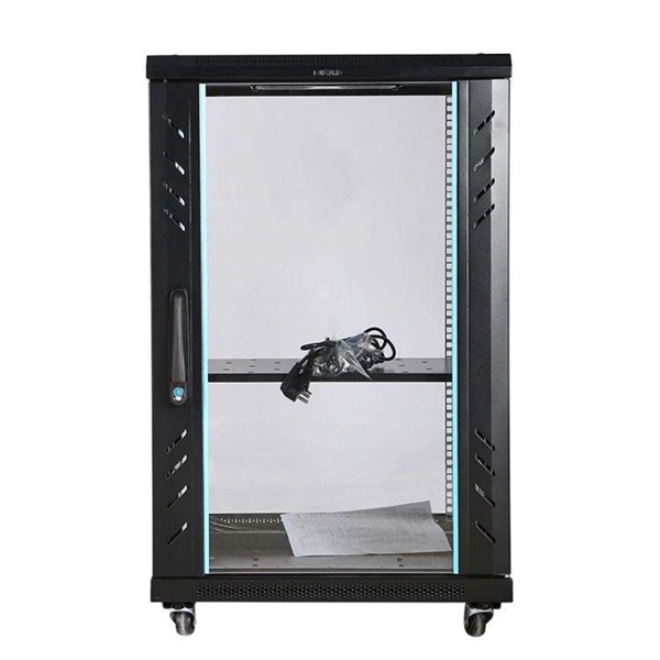
It is not recommended to place your router inside a cabinet as it can lead to poor Wi-Fi signal strength and potential overheating issues. Cabinets typically have materials that can interfere with the Wi-Fi signal, resulting in reduced coverage and slower internet speeds. For optimal performance. 💧 Water absorbs WiFi signal. Large aquariums or other significant water sources near your router can cause real connectivity issues, since water molecules are particularly effective at absorbing radio wave energy. 🏠 Router placement is your single most controllable variable. Careful planning ensures your router stays cool and your internet connection remains. Whether you're using a single Wi-Fi router or a mesh network, positioning your hardware correctly can make a major difference in speed, reliability, and coverage. Hiding your router in a cabinet or tucking it behind your TV might look tidy, but it's probably weakening your signal. After years of. In our increasingly connected world, a strong Wi-Fi signal is essential for everything from remote work to streaming entertainment. Yet many homeowners unknowingly place items near their routers that can significantly weaken their internet connection. Understanding what objects interfere with your. Positioning your router behind large furniture, under shelving units, or enclosed within cabinets can substantially degrade its performance.
[PDF]

This manual describes the protection, automation, control, and monitoring functions of the SIPROTEC 5 devices. In order to protect technical infrastructures, systems, machines and networks against cyber threats, it is necessary to implement – and continuously maintain – a holistic, state-of-the-art. Busbar Differential Protection Definition: Busbar differential protection is a scheme that quickly isolates faults by comparing currents entering and leaving the busbar using Kirchoff's current law. Current Differential Protection: This protection method connects CT secondaries in parallel and. A busbar protection is a protection to protect busbars at short-circuits and earth-faults. In the “childhood” of electricity no separate protection was used for the busbars. With increasing short-circuit power in the network. SIPROTEC 7SS60 7SS60 is a numerical differential current protection for busbars. It is suitable for all voltage levels and can be adapted to a large variety of busbar configurations. Busbar protection is critical for the safe and reliable operation of a power system. Related Article: Busbar Protection Like any other faults. Bus bar protection scheme shall be provided for 220KV system where the sub-station layout arrangement is with 3-bus system (Main 1, Main 2 & Transfer Bus) or two bus system with Main bus with bus section breaker & Transfer bus.
[PDF]

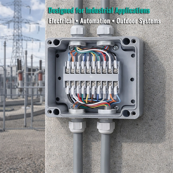
A typical fiber optic splice enclosure consists of several key components that work together to protect and organize the fiber splices. Standard enclosures contain: 1) Housing, 2) Cable fixation clamps, 3) Splice trays, 4) Sealing system. A splice box (also known as splice distributor) is a housing in which fiber optic cables begin or end. Fiber optics are fanned out in splice boxes that are situated at the end of fiber optic transmission paths. Optical cable joint box The optical cable joint box permanently connects two optical cables together and has a joint part for protecting components. The optical cable connection part, that is, the optical cable joint, is the part where the. An optical cable split fiber box, also known as a fiber distribution box or fiber optic splice closure, is a device used to terminate, splice, and distribute optical fibers. In this response, we will focus on the. This guide optimizes the original text by delving deeper into the three pillars of fiber network longevity: the impact of splicing technology, the strategic selection of splice boxes, and the essential maintenance protocols needed to ensure sustained, high-speed functionality. Fibre optic cables are manufactured in standardized lengths –.
[PDF]

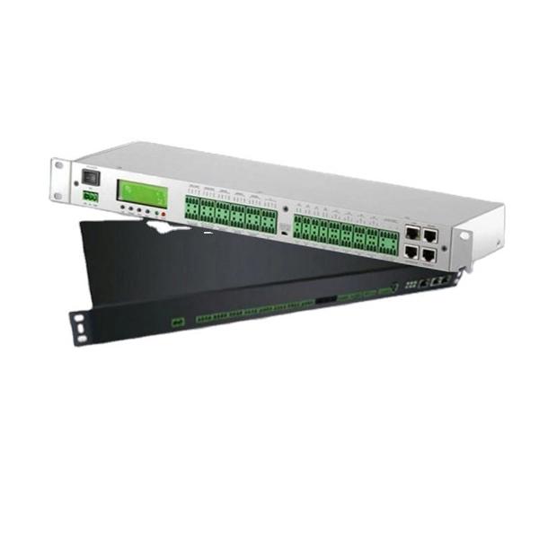
It connects to two independent power sources, enabling automatic switching to a secondary source during primary source failures. This seamless transition prevents disruptions to connected devices and enhances operational reliability. A dual power switching box is precisely the kind of gadget that guarantees a constant flow of electricity as it enables the user to shift the operational state between two different energy supplies. It can be found in homes, workplaces, factories, and anywhere else where sudden cuts of energy can. The ATS Dual Power Distribution Box plays a pivotal role in providing efficient low-voltage power solutions, ensuring that power flows seamlessly, even in the event of an outage. This comprehensive guide offers insights into the mechanisms and benefits of the ATS Dual Power Distribution Box. Transfer switches and sub panel boxes are key components in dual power switching cabinets. Transfer switches automatically switch between power sources during outages, ensuring uninterrupted power and system reliability. This redundancy ensures that if one power source fails, the other can immediately take over, minimizing downtime and preventing. A dual power switch helps you manage two power sources for one system. You can use it to keep your equipment working if the main power stops. This device quickly changes from the main supply to a backup source. This seamless transition.
[PDF]

Attenuation describes the continuous loss along the fiber, while insertion loss describes the additional loss caused by components such as connectors, splices, or splitters. In fiber optic networks, particularly in FTTx (Fiber to the x) and PON (Passive Optical Networks) deployments, splitters play a central role in distributing the optical signal from a single source to multiple destinations. The split ratio and insertion loss are two key parameters defining their performance. A deeper understanding of these. This document describes how to calculate the maximum attenuation for an optical fiber. You can apply this methodology to all types of optical fibers in order to estimate the maximum distance that optical systems use. There are no specific requirements for this document. This document is not. By dividing a single optical signal from a central Optical Line Terminal (OLT) into multiple outputs for Optical Network Terminals (ONTs) at users' homes, splitters eliminate the need for dedicated fibers to each residence—slashing infrastructure costs while scaling network reach. Losses can be introduced by various means such as intrinsic material absorption, scattering, bending, connector loss and more. The tutorial has the following parts: When light propagates as a guided wave in a fiber core, it experiences some power losses. These are particularly important for long-haul data transmission through fiber-optic telecom.
[PDF]

5 dB depending on splitter type. Common planning value: 0. Optional: patch panels, attenuators, or extra components. Helps cover dirt, aging, and measurement tolerances. Adds Rx power and margin calculation. Use 2×N when two inputs feed the same distribution stage. Wavelength is recorded in outputs for documentation. Optional: patch. FTTH / PON Splitter Loss Calculator - Zion Communication is a professional manufacturer of cables and accessories for signal and low voltage transmission. Estimate whether an FTTH or PON optical link is feasible by calculating PLC splitter loss, fiber attenuation, connector loss, splice loss and. In fiber optic networks, particularly in FTTx (Fiber to the x) and PON (Passive Optical Networks) deployments, splitters play a central role in distributing the optical signal from a single source to multiple destinations. These are known as passive optical splitters, and they perform the function. The formula for the theoretical loss for each output port of a splitter with N output ports is: Theoretical Split Loss (in dB) = 10 * log10 (N) Where: N is the number of output ports the splitter has (e., 2 for a 1x2 splitter, 4 for a 1x4, 8 for a 1x8, 32 for a 1x32, etc. Passive split links usually lose the most dB at the splitter, so we keep the optical budget and the installed route separate. These are especially important for FTTH (Fiber to the Home), data centers, and Passive Optical Networks (PON), where.
[PDF]
A beam splitter does not act as a hole. Beam splitters crucially have an (internal) interface between the materials with 2 diffraction indices. Ok, in a double slit you have 2 holes in a wall, and thus there are 2 ways through which the particle to go. But in a beam splitter where are those 2 holes ? So my question is: at the molecular/atomic level, what is there in the beam splitter that makes it act as 2 holes in order for the particle. A beam splitter or beamsplitter is an optical device that splits a beam of light into a transmitted and a reflected beam. In its. Beamsplitters are fundamental components in optical engineering, serving to precisely divide a single input beam of light into two distinct output beams. This division allows for the simultaneous analysis or utilization of the light's properties along two separate paths. The device is purely. Modern microscopes have a variety of objectives, mirrors, and pinholes in order to obtain the best image (Figure 1B). The component of interest here is the beam splitter. Figure 1: The light path through different microscopes. A) An early compound microscope with a basic light path. In its. The item may have some signs of cosmetic wear, but is fully operational and functions as intended. This item may be a floor model or store return that has been used. See the seller's listing for full details and description of any imperfections. - Feedback replied by seller phase-space-optics.
[PDF]

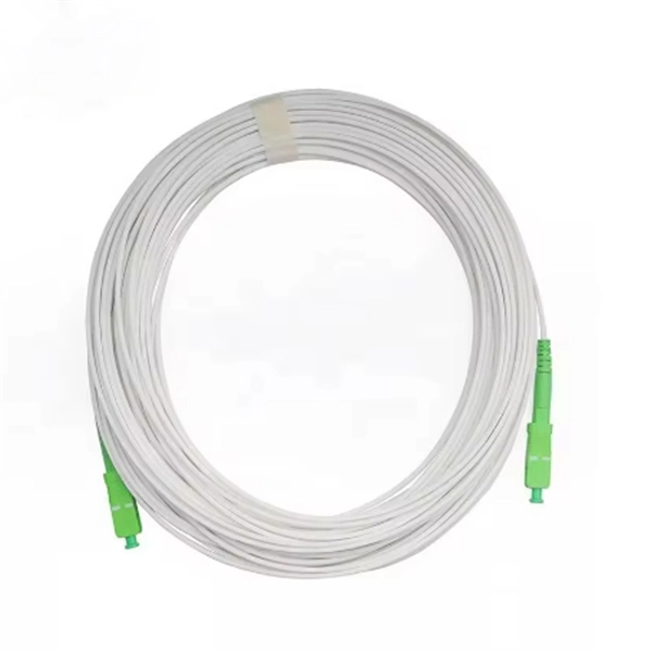
This unit is a nine output Composite Splitter with built in distribution amplifier. It is used to distribute composite video signals to multiple destinations with compatible outputs. Composite Splitter provides multiple outputs that are identical to the Video input signal. Check each product page for other buying options. Shop products from small business brands sold in Amazon's store. Learn more Need help? Discover optical fiber splitters designed for home. Optical splitters and couplers split or combine light—distributing signals injected into a single fiber strand to multiple fibers, enabling point to multi-point communication in Fiber To The Home (FTTH) networks based on ITU. T PON standards such as GPON, XGS-PON and new 25 and 50G standards. Cables Plus USA can supply custom fiber optic splitters to meet your specific requirements. Available in PLC splitters, also called Planar Lightwave Circuit. As well as FBT splitters Fused Biconical Taper splitters, which are two or. Only 1 left! Get the best deals on Corning Cable Splitters and Adapters and find everything you'll need to improve your home office setup at eBay. Fast & Free shipping on many items!. FS PLC Fiber Optic Splitters, Bare/Blockless/ABS/LGX Splitter/Rack Mount Types, support 1xN light distribution, with low IL and PDL for high-reliability transmission. Deploying compact FS PLC Splitters to simplify your networks, perfectly fits your PON, EPON, FTTX, etc. ZIP code to view pricing.
[PDF]

With the large variety of beamsplitters available, the designer needs to take many factors into consideration. This article and its illustrations will go a long way toward making the correct choice less of a risk. All curves show typical performance. A beam splitter (or beamsplitter, power splitter) is an optical device which can split an incident light beam (e. a laser beam) into two (or sometimes more) beams, which may or may not have the same optical power (radiant flux). It is a crucial part of many optical experimental and measurement systems, such as interferometers, also finding widespread application in fibre optic telecommunications. One beam is typically reflected while the other is transmitted. Beamsplitters are often classified according to their construction: cube or plate. In this blog, we will explore the step-by-step process of using a beamsplitter cube effectively, along with some common applications that benefit from this powerful optical tool. Step-by-Step Guide on Using a Beamsplitter Cube Step 1: Understanding the Cube Orientation: A beamsplitter cube is a. A beam splitter is an optical device that splits beams (such as laser beams) into two (or more) beams. Beam splitters typically come in the form of a reflective device that can split beams into exactly 50/50, half of the beam being transmitted through the splitter and half being reflected.
[PDF]
In its most common form, a cube, a beam splitter is made from two triangular glass prisms which are glued together at their base using polyester, epoxy, or urethane-based adhesives. (Before these synthetic resins, natural ones were used, e. ). A beam splitter or beamsplitter is an optical device that splits a beam of light into a transmitted and a reflected beam. It is a crucial part of many optical experimental and measurement systems, such as interferometers, also finding widespread application in fibre optic telecommunications. In its. 📦 For purchasing, use the RP Photonics Buyer's Guide for beam splitters. It provides an expert-curated supplier directory, buyer-focused technical background information, and structured selection criteria to support professional procurement decisions. Light from an input fiber is first collimated, then sent through a beam splitting optic to divide it into two. The resultant output beams are then focused back into the output fibers. Note that jT j2 is the transmitted intensity. Similarly, E2 ! RE3 + T E4. The transformation matrix is then given by The elements of the beam splitter transformation matrix B are determined using the.
[PDF]
A fiber router includes an actual port for this connection, so you won't need an adapter that translates Ethernet into fiber optic signals or vice versa. It should be a truly plug-and-play experience, so long as you have a fiber optic modem and the accompanying service plan. Fiber internet transmits data using light signals through fiber-optic cables, which differs from traditional DSL or cable internet. Instead of a modem, fiber connections require an Optical Network Terminal (ONT), a device that converts fiber signals into an Ethernet connection. Most fiber ISPs. Which either needs a fiber optic port, or an SFP port, plus a fiber otpic-to-sfp tranceiver. Given that, how come 95% of the 5G, 1Gb/s routers I see in stores still only have ethernet ports? Rather than moving to fiber or SFP ports, consumer industry decided to go with NBASET running 2. Here's what you need to know: A fiber router, or fiber optic router, is a router that is specifically equipped. Fiber vs. Cable Internet: Here's a modem connected to a service line and a Wi-Fi router's WAN port. A cable modem generally includes a service port (for the coax line) and one or more RJ45 network ports to connect to a router. 1 with its multi-Gigabit capability is the. The good news is that once you're set up with an ONT, you're good to go for the future—you can simply plug any wireless router you like into its Ethernet port to set up a wireless fiber home network.
[PDF]