This report provides an in-depth analysis of the Passive Optical Component market, examining current trends, market dynamics, and future projections from 2023 to 2033. It offers valuable insights into market size, growth, and technological advancements shaping the industry. Global Optical Passive Device market was valued at USD 8,139 million in 2024 and is projected to reach USD 18,950 million by 2032, exhibiting a CAGR of 13. 1% during the forecast period. Optical passive devices are components that manipulate light signals without requiring external power sources. The Passive Optical Components Market exhibits a complex revenue landscape driven by diverse product categories, application domains, end-user industries, and regional dynamics. A precise understanding of segment-wise market share, revenue distribution, and growth potential is critical for. The passive optical components market is projected to grow from USD 64. 8 billion in 2025 to USD 210. Optical Cables will dominate with a 48. 17 Bn by 2033, exhibiting a compound annual growth rate (CAGR) of 17. The passive optical.
[PDF]
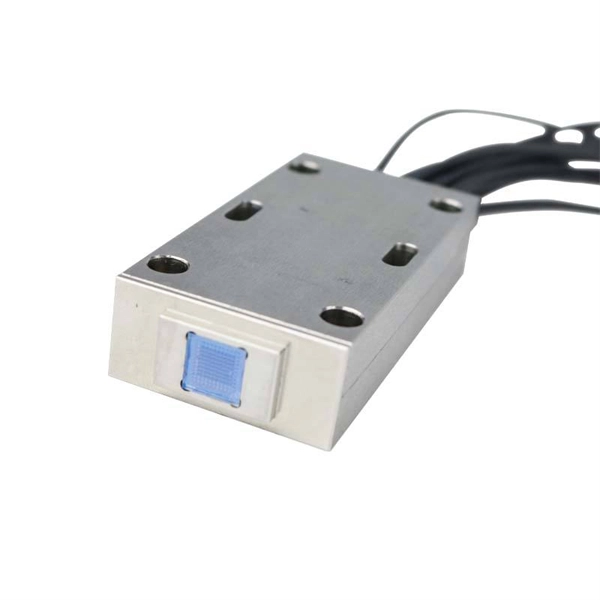
Compare products based on your own technical specification criteria. How does our search work? With MEET OPTICS search you get direct access to our database of thousands of optical components from providers worldwide. Prices and product specifications directly listed from optical component. The passive optical components market is projected to grow from USD 64. 8 billion in 2025 to USD 210. Optical Cables will dominate with a 48. The Passive Optical Components. These components function by transmitting, reflecting, splitting, or redirecting optical signals without the need for active electrical circuits. Common examples of passive optical components include optical fibers, optical splitters, couplers, and multiplexers. These components are essential in. A socket specifically developed for virtual production. Radio Receiver transmits tracking data from all connected Antilatency radio sockets to the target program on the PC. 6% during the forecast period. Passive components are the foundation stone of optical network systems. Most of. VIPER™ is the fastest, most accurate electromagnetic tracker in the world. With its sleek, small size, continuous tracking data of rates up to 960 frames per second, and latency as low as one millisecond, VIPER offers scaled-up capability in a scaled-down package. With added Fly True Technology.
[PDF]

A single strand of glass fiber, called single-mode fiber, is used to transmit single-mode or light beams. It can transmit higher bandwidth than multimode fiber but requires a light source with a limited spectral range. There are mainly two types of optical fibers, single-mode optical fiber, and multimode optical fiber, which differ in the way light propagates. The latter is used for short-distance transmission, while the former is typically used for long-distance signal transmission. Please refer to the article. Single fiber modules (BiDi) use one fiber for both transmitting and receiving data. This saves space and money. Dual fiber modules use two fibers. They are easier to set up and give steady communication. Single-mode optical modules are best for long distances and fast speeds. Modes are the possible solutions of the Helmholtz equation for waves, which is obtained by combining. Optical fiber transmission is based on the principle of total internal reflection, where light signals are transmitted through a thin glass or plastic fiber with a core and cladding. The core has a higher refractive index than the cladding, causing the light signal to be reflected back into the. OS1 single mode fiber optic cables are made with a single mode fiber core, which means that they have a very small core diameter of 9 microns. Each type serves distinct applications based on its light transmission characteristics. Very small core (~8–10 µm). Carries one light path (mode).
[PDF]

Optical transmission windows are specific wavelength ranges where light travels through fiber with minimal attenuation (signal loss) and dispersion (distortion). These low-loss windows are essential for maintaining the performance and reach of fiber optic communication systems. Fiber optic cable is a type of cabling that contains one or more optical fibers for transmitting data at high speeds and/or over long distances using light. These fibers are most commonly made of glass and are very thin, typically less than a tenth of the width of a human hair. Fiber optic cable. This is your "QuickStart" guide to testing fiber optic cable plants, patchcords and communications equipment with a fiber optic light source and power meter. We'll give you the basic information you need and provide some printable references. Optical power, required for measuring source power, receiver power and, when used with a test source, loss or attenuation, is the most. Fiber optic loss testing is an essential part of maintaining reliable, high-performance fiber optic networks because it helps identify potential issues and ensures that the system meets the required performance specifications. In this blog, we'll explore what a power meter and light source are and. This part of IEC 61280 is applicable to the measurement of attenuation of installed optical fibre cabling plant using multimode optical fibre.
[PDF]
Usually, the 10G/25G grey light optical modules with a short transmission distance are applied for connecting AAU/DU with WDM/OTN/SPN. The connections between WDM/OTN/SPN network devices can be achieved by 10G/25G/50G/100G dual-fiber or single-fiber bidirectional. Compared with Draft A (2013-07-30), this issue includes the following new topic: 2. This section describes engineering specifications of an AAU, including input power and equipment specifications. 7. In 2/3/4G networks, 10Gbps optical modules are generally enough for CPRI interfaces. In 5G networks, CPRI is also upgraded to eCPRI. Currently, 5G of the bearer network mainly uses 25Gbps optical modules. Next, ETU-LINK will introduce the types of optical modules used by 10G SFP+ and 25G SFP28. What is the difference between the 5G bearer network and the traditional optical transmission network? The main difference is that 5G fronthaul needs to support CPRI/eCPRI protocol. Most of the AAU of 5G base stations are deployed outdoors. In order to resist harsh environments such as high. The optical modules used to connect BBU and RRU devices are optical modules and optical fibers. Product Versions The following table lists the product versions related to this document. 25G SFP optical module adopts the wavelength of 850nm, with an operating.
[PDF]
Single fiber modules (BiDi) use one fiber for both transmitting and receiving data. This saves space and money. Dual fiber modules use two fibers. They are easier to set up and give steady communication. In DWDM implementations, each direction of communication occupies a dedicated fiber, improving the stability of the transmission. This configuration is widely adopted in traditional telecom. Single-fiber WDM (also known as bidirectional or BiDi WDM) uses one physical optical fiber strand to transmit and receive signals simultaneously—often employing different wavelengths for upstream and downstream. How It Works: Two distinct wavelengths (e., 1270 nm and 1330 nm) are used in opposite. Single fiber module also called BiDi transceiver or WDM module. It uses WDM technology to realize the bidirectional transmission of optical signals on one optical fiber. BIDI module only has 1 port, wave filtering through the filter of module, and finished the transmitting of 1310nm optical signal. While both are designed for transmitting data over fiber optic cables, SFP bidi vs duplex differ significantly in how they operate and are deployed. In this article, we break down What Is an SFP BiDi Module and SFP Duplex Module? When Should You Use SFP BiDi and When Should You Use SFP Duplex? to. It has two distinct channels or ports, TX is used for transmission and RX for reception. For example: TX1310nm/RX1550nm TX1550nm/RX1310nm. Single fiber optical.
[PDF]
In STP, copper wires are first covered by plastic insulation. A metal shield, which consists of metal foil or braid, surrounds the bundle of insulated pairs. Where electromagnetic radiation is a serious issue, eac.
[PDF]
Optical switches will accept inputs nearly immediately as compared to mechanical switches, which could experience a few milliseconds of debouncing lag. Since optical switches do not depend on physical contact, input latency (latency) is severely minimized. This discrepancy can just be a couple of. An optical transistor, also known as photonic transistor, optical switch or light valve, is a device that switches or amplifies optical signals. Any communication protocol (Ethernet, ATM, etc. Significant. High Speed: Optical switches provide a high-speed data transmission capacity that surpasses that of traditional electrical switches. Interference Resistance: They are immune to electromagnetic interference, ensuring a reliable data transfer. Low Power Consumption: With no need for O-E-O conversion. Optical switching is the process of controlling the destination of individual optical information signals. This technology allows for high bit rate transmission to be switched between various optical lines. The core component enabling optical switching is the Optical Switch. Figure: Optical Switch. Serving as the backbone of high-speed fiber-optic networks, data centers, and emerging technologies like quantum communication, optical switches enable efficient light signal management with a small latency. As global demand for bandwidth surges due to 5G, AI, and cloud computing, advancements in.
[PDF]
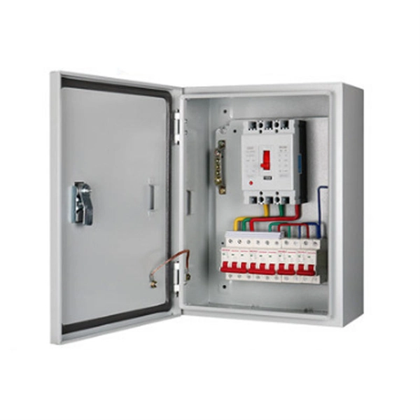
A passive optical network (PON) is a fiber-optic telecommunications network that uses only unpowered devices to carry signals, as opposed to electronic equipment. In practice, PONs are typically used for the last mile between Internet service providers (ISP) and their customers. In this use, a PON has a point-to-multipoint topology in which an ISP uses a single device to serve many end-us. Components and characteristicsA passive optical network consists of an (OLT) at the service provider's central office (hub), passive (non-power-consuming) optical splitters, and a number of (ONUs) or. Passive optical networks were first proposed by in 1987. Two major standard groups, the (IEEE) and the. A PON takes advantage of (WDM), using one wavelength for downstream traffic and another for upstream traffic on a (ITU-T, typically OS2). BPON, EP.
[PDF]
PAM4 is a modulation scheme that combines two bits into a single symbol with four amplitude levels as shown in Fig. This effectively doubles a network's data rate, enabling 400G/800G short-haul transmission. NRZ, or Non-Return-to-Zero signaling, represents binary information using two distinct signal levels: This creates relatively wide signal separation between logical states. As a result, NRZ systems historically provided: This operational tolerance helped earlier architectures remain relatively. PAM4 is a branch of the pulse amplitude modulation (PAM) technology, which is a mainstream signal transmission technology following non-return-to-zero (NRZ). Playing a key role in multi-order modulation, PAM is widely used in high-speed signal interconnection. Figure 1-1 shows the typical waveform. A key new modulation scheme, PAM4, was introduced around 2017 and enabled the big jump from 100G to 400G. When it comes to enabling 400G and higher Ethernet speeds, a four-level pulse amplitude modulation or PAM4 multilevel signaling is needed as opposed to the non-return-to-zero (NRZ) modulation.
[PDF]
Passive optical networks were first proposed by in 1987. Two major standard groups, the (IEEE) and the of the (ITU-T), develop standards along with a number of other industry organizations. The (SCTE) also specified f.
[PDF]

When the optical switch module's switching interfaces are all busy or an optical signal needs signal regeneration through an OEO conversion process, the electronic module is used. In modern optical transport networks, optical cross‑connect (OXC) devices are essential for high-speed, flexible signal routing. An OXC switches optical signals between fiber inputs and outputs without converting them to electrical signals, enabling true all-optical routing. In the 1980s, when transmission speeds supported by optical fibers increased from 45 Mbit/s to 2. In essence, an OXC uses photonic switching fabric to route wavelength channels from any incoming fiber to any outgoing fiber. OXC (optical cross-connect) is an evolved version of ROADM (Reconfigurable Optical Add-Drop Multiplexer). As the core switching unit of the optical network, the scalability and economic efficiency of the optical cross-connect (OXC) not only determine the flexibility of the network topology, but. Vendors such as LINK-PP provide comprehensive transceiver and interconnect solutions that ensure OCS architectures perform at their highest potential. This article explores OCS fundamentals, its benefits, use cases, and how LINK-PP optical module solutions complement these networks. Compared with traditional ROADM based on separate boards and inter-board fiber patch cords, OXC uses integrated interconnections to build an all-optical switching resource pool, achieving highly integrated, fiber.
[PDF]

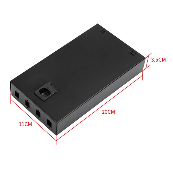
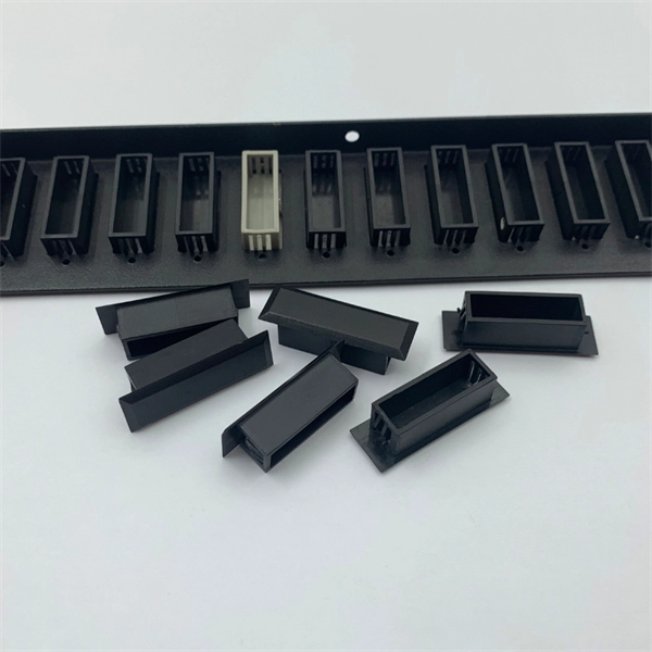
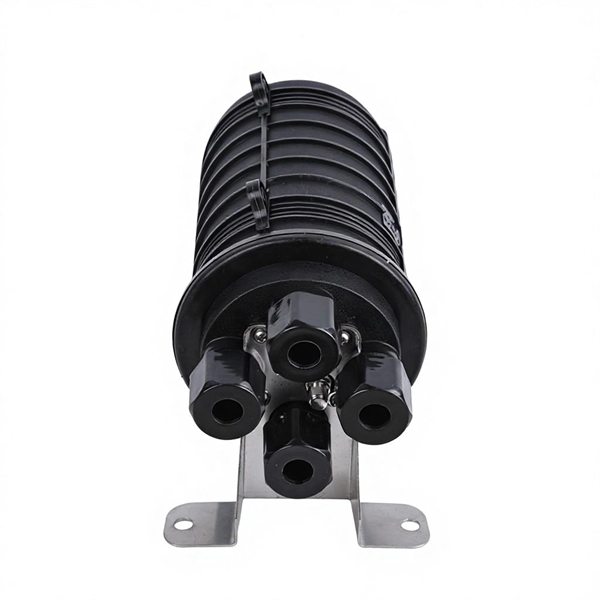
The main components of a splice box are the splice cassette that picks up the fibers and their reserves, and the front panel which contains different connectors for transmitting signals via copper or fiber optic cables. A splice box (also known as splice distributor) is a housing in which fiber optic cables begin or end. Fiber optics are fanned out in splice boxes that are situated at the end of fiber optic transmission paths. It typically consists of two parts: an outer housing and an internal structure. In this response, we will focus on the. The FSB series of indoor wall mount enclosures are designed for centralized splice-only applications. These boxes are well suited as optical cable splice collection points for DAS (Distributed Antenna Systems), MTU (Multi-Tenant Unit) commercial business applications, and MDU (Multi-Dwelling Unit). Fiber optic splice closures permanently connect two fiber optic cables together and have a splice that protects the components. The optical cable connection part, that is, the optical cable joint, is the part that protects the connection between two or more optical cables by the optical cable. Splicing refers to the permanent connection of two optical fibers to form a continuous optical connection.
[PDF]

As illustrated in typical SFP internal structure diagrams, the module's core components include an optical transmitter assembly (TOSA), laser driver, optical receiver assembly (ROSA)—some high-sensitivity modules (like L16. 2) use APD receivers, which require an additional booster. The optical module serves as a crucial component in optical fiber communication systems, operating at the physical layer, which is the lowest layer in the OSI model. Its primary function is to achieve optoelectronic conversion by converting electrical signals into optical signals and vice versa. Among various optical module form factors, SFP (Small Form-Factor Pluggable). The function of the optical module is to carry out the photoelectric and electro-optic conversion. In this article, ETU-LINK will introduce to you what are the core components of the optical module? 1. TOSA: Its main function is to convert electrical signals to optical. the embodiments of the present applicationprovide an optical emission module, an emission device, a detection device and a terminal, which can improve the energy density of a light spot formed by an emission light beam and improve the integration of the device. an embodiment of the present.
[PDF]
A switch must use optical or copper modules that have been certified for use on Huawei S switches. Non-certified optical or copper modules cannot ensure transmission reliability and may affect service stability. Huawei is not liable for any problem caused by the use of non-certified optical or. In the era of 5G, AI, and high-speed data centers, optical modules serve as the core bridge for converting electrical signals to optical signals (and vice versa), enabling fast, reliable data transmission across networks. Huawei is not liable for any problem caused by the use of non-certified optical or. The Cisco ® 40GBASE QSFP (Quad Small Form-Factor Pluggable) portfolio offers customers a wide variety of high-density and low-power 40 Gigabit Ethernet connectivity options for data center, high-performance computing 00networks, enterprise core and distribution layers, and service provider. SFP (Small Form-factor Pluggable) is a compact, hot-pluggable network interface module used to connect network devices (switches, routers, firewalls) to fiber optic or copper cables. Think of it as the “translator” for your network equipment, converting electrical signals into optical signals. The optical module serves as a crucial component in optical fiber communication systems, operating at the physical layer, which is the lowest layer in the OSI model.
[PDF]