This paper analyzes the basic principle and function of relay protection, summarizes the common fault types, and analyzes the fault analysis methods and treatment measures combined with actual cases. A method of fault tracking for relay protection devices is presented in this paper. Fault tracking means that after the failure of relay protection devices, the anomalies and warning informa-tion are obtained through data-mining technology, and then, the fault tracking algorithm is used. Relay fault diagnosis refers to the process of identifying and analyzing faults or abnormalities in protective relays. However, in actual operation, the relay protection device may cause failure due to hardware failure, software problems or external. For a long time, the fault diagnosis technology of relay protection consists of isolated cases and does not have a systematic method.
[PDF]

Numerical relay are embedded with specialized digital signal processor (DSP) as the computational hardware. By using DSP as the relay's processor, the relay is capable of meeting the fundamental protective requirements such as reliability, sensitivity, selectivity and speed . Thus, various protective devices are used to protect the power system, of which digital signal processor (DSP) numerical relays are capable of significantly improve protection operations. Therefore. Manuals and User Guides for Samwha DSP DSP-VIP-PM Motor Protection. We have 1 Samwha DSP DSP-VIP-PM Motor Protection manual available for free PDF download: Manual Samwha dsp DSP-VIP-PM Motor Protection Pdf User Manuals. View online or download Samwha dsp DSP-VIP-PM Motor Protection Manual. Many of the new protection relays are microprocessor based and are generally referred to as numerical relays. This means that signals from transducers are sampled at fixed time intervals, digitally encoded, and processed by equipment which resembles a computer to derive relaying information, e.
[PDF]

Work From Home Relay Protection Engineers often face challenges related to coordinating with on-site teams, accessing physical equipment remotely, and ensuring clear communication during installations and troubleshooting. In this comprehensive article, we delve into the best practices, challenges, and innovative solutions in relay testing and commissioning, placing a strong emphasis on. Relay protection is the discipline of designing schemes that detect faults, coordinate relays, and isolate equipment without outages. It emphasizes selectivity, coordination, fault response, and system behavior rather than individual relay devices. Relay protection is often misunderstood as a. What are the top challenges that a Protective Relay Technician might face in the first 90 days? What does a day in the life of a Protective Relay Technician look like? What are some tips for helping a Protective Relay Technician fit into the company culture? What are some career development tips. fer more functions than ever. Substation Protection and Control (P&C) systems based on the IEC 61850 standard and energy sources from inverter-based renewable of engineers and technicians. In complex power networks, coordination between protective devices becomes essential to ensure selective operation and minimize disruptions. However, achieving coordination.
[PDF]
Distance relays, also known as impedance relay, differ in principle from other forms of protection in that their performance is not governed by the magnitude of the current or voltage in the protected circuit but rather on the ratio of these two quantities.OverviewIn, a protective relay is a device designed to trip a when a is detected. The first protective relays were electromagnetic devices, relying on coils operating on moving par. Electromechanical protective relays operate by either, or. Unlike switching type electromechanical with fixed and usually ill-defined operating voltage thresholds.
[PDF]
Distance relays, also known as impedance relay, differ in principle from other forms of protection in that their performance is not governed by the magnitude of the current or voltage in the protected circuit but rather on the ratio of these two quantities.OverviewIn, a protective relay is a device designed to trip a when a is detected. The first protective relays were electromagnetic devices, relying on coils operating on moving par. Electromechanical protective relays operate by either, or. Unlike switching type electromechanical with fixed and usually ill-defined operating voltage thresholds. Electromechanical relays can be classified into several different types as follows: "Armature"-type relays have a pivoted lever supported on a hinge or knife-edge pivot, which carries a moving contact. These relays may.
[PDF]

FS optical line protection switch features 1+1 backup and less than 15 ms fast switch to the standby fiber link that ensures business uninterrupted when malfunction occurs. An optical protection switch is a critical component in fiber optic communication systems designed to safeguard optical signals and infrastructure from damage due to power surges, signal overloads, or system failures. These switches ensure signal integrity, minimize downtime, and enhance network. 1+1 Optical Line Protection System for Fiber Protection, Bi-directional Protection in Dual Fiber, LC/UPC, Pluggable Module OLP (Optical Line Protection) is a device used in pairs, one at each end of the optical signal to protect network transmission line. OLP products include fiber optical line protection switches, optical bypass switches, optical cross connection, multi-channel. The FOSW-1x1 or 1x2 optical switch is based on opto-mechanical technology with proven reliability. OSW-W1x2 optical switch is a high performance electro-optical device, with low insertion loss (typic. In optical communication network, OLP monitors optical power of optical fiber and standby.
[PDF]

Generator protection relays are devices that detect abnormal operating conditions and isolate the generator from the system to prevent damage. These relays act as the first line of defense and are installed with strict adherence to IEC Standard for Protection Relays. Protecting generators from different electrical, mechanical, and thermal stresses is known as generator protection. To safeguard machines from overloads and unusual circumstances, preventive measures are required. Faults are inevitable even with effective design, construction, and operation. Below is an overview of the different types of relays used in generator systems, their functions, and their specific applications. Electromagnetic relays use. Generator Protections are broadly classified into three types: Class A, B and C. Class A covers all electrical protections for faults within the generating unit in which generator field breaker, generator breaker and turbine should be tripped. What Are Generator Protection Relays? Generator protection. There are various protection relays and those are used for protection against a wide variety of conditions. The fundamental principles that are covered in this course are equally applicable to. IEEE C37. 2 defines the IEEE “numerical” function designation for all protective relay functions. This presentation primarily uses the designations from the Beckwith M-3425A relay, which in most cases follows IEEE C37.
[PDF]
Thermal relays are the perfect solution for providing protection to motors which provides the most precise tripping for the electric motor during single phasing and overload. This article discusses an overview.
[PDF]
The original unstructured record data for the defect of the relay protection devices (RPDs) may contain problems influencing the data mining, and it is lack of quantitative evaluation. So the purpose of this.
[PDF]
For high intracavity powers (e. tens of watts), however, detrimental thermal effects can occur, such as a shift of the reflection band and a decrease of reflectance. For not too high power levels, volume Bragg gratings can also be used in spectral beam combining. There are fiber Bragg gratings. An optical fiber grating is a small segment within an optical fiber altered to act as a selective filter for light. This treated area functions like a specialized mirror, reflecting a specific wavelength of light while allowing all other wavelengths to pass through. This microscopic structure. Optical fiber grating technology serves as a foundational stone in modern communication and sensing systems. This technology relies on periodic structures within optical fibers that modify the propagation of light, enabling a myriad of applications ranging from telecommunications to environmental. Fiber Bragg grating (FBG) sensors have emerged as advanced tools for monitoring a wide range of physical parameters in various fields, including structural health, aerospace, biochemical, and environmental applications. This review provides a comprehensive overview of FBG sensor technology. A fiber Bragg grating (FBG) is a type of distributed Bragg reflector constructed in a short segment of optical fiber that reflects particular wavelengths of light and transmits all others. This can be achieved by making use of fiber photosensitivity. At each interface between two regions.
[PDF]
Check the electrical load and ensure that the sensors do not exceed the 10 Amp maximum. Check each wire for damage that may lead to a short. Check the tightness of electrical connections along the power supply. Each powernet distribution box (PNDB) on the vehicle provides up to 4 low amperage circuits (30 amp and less), and up to three high amperage circuits through midi fuses. The fuses are located behind a cover on the face of the PNDB. On vehicles equipped with a cab load disconnect switch (CLDS), the. These limits are designed to provide reasonable protection against harmful interference when the equipment is operated in a commercial environment. This equipment generates, uses and can radiate radio frequency energy and, if not installed a nd used in accordance with the instruction manual, may. I currently dont have any power to the distribution box. For some reason, I cant find the issue why there is no power into the distribution box. The wire that is attached to the box near the fender, does have power. Here are some solutions when a power distribution box fails: Safety First: Make sure you are safe. However, in actual applications, distribution boxes often encounter a series of problems, which not.
[PDF]

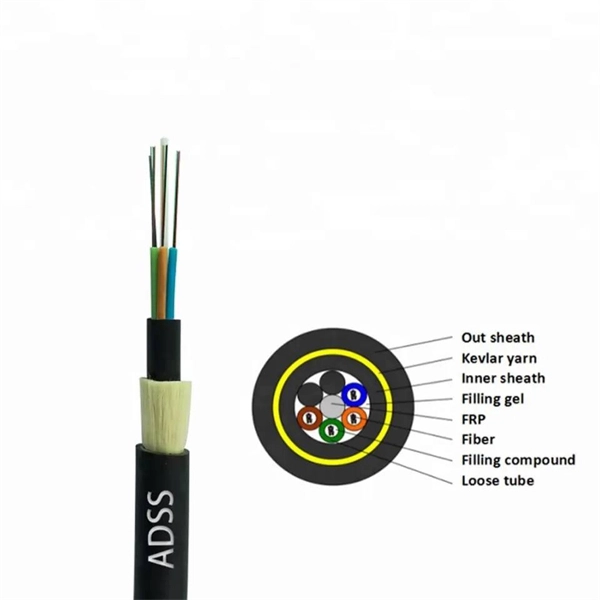
Selecting the right cable type ensures that the structure itself provides first-level protection. UV-Resistant Jackets (PE or LSZH): Prevent sunlight degradation. Water-Blocking Gel or Tape: Stops moisture migration inside the cable. Metal or Non-Metallic Armoring: Adds crush and. This guide covers how to safeguard outdoor fiber optics across underground, aerial, direct-burial, and exposed setups. Before applying protective measures, it's essential to understand the main risks fiber optic cables face outdoors. UV Exposure: Prolonged sunlight degrades standard plastic. Fiber optic cables are often used for long-distance communication due to their high bandwidth and low signal attenuation. Outdoor fiber optic cables are installed in harsh environments where they are exposed to various environmental factors such as temperature changes, humidity, moisture, dust, and. Optical cable lines lightning protection and strong current protection are achieved by avoiding, guiding or discharging them underground to prevent lightning and strong current from causing damage to the optical cable lines themselves, communication equipment and personnel. Since the lightning. The Fiber Optic Association, Inc. (FOA) was founded in 1995 to help develop the workforce to build the fiber optic networks to support a rapid expansion in communications and the Internet. Introduction: Why Fiber-Optic Cable Damage Matters Fiber-optic cables transmit data via pulses of light.
[PDF]

This guide provides clear cost ranges in USD and practical pricing details for U. Typical cost range for a single relay is $2–$150 depending on type and rating. Buyers typically pay a range for relays, and cost is driven by relay type, coil voltage, contact rating, and packaging. This guide presents practical price estimates in USD, with low–average–high ranges and real-world factors that affect total cost. Assumptions: region, specs, labor hours. Relays. The SEL-351 Protection System has built-in Ethernet and IEEE C37. 118 synchrophasors, and is ideal for directional overcurrent applications. Optional Mirrored Bits communications and power quality monitoring add flexibility to solutions. The SEL-351 is the protection standard for utility and. Buyers typically pay a modest amount for small signal relays and higher sums for industrial or specialty units. The main cost drivers are the relay category (signal, automotive, or industrial), quantity, and installation requirements. Although failure of a protective relay system may have severe local or regional impacts, most protective relay systems are not required to operate to prove they are in working order. Ensuring that. What are Protection Relays and How Do They Work? Protection relays are specialized devices designed to detect abnormal conditions in electrical systems and initiate appropriate actions to protect equipment and personnel. These intelligent sentinels continuously monitor electrical parameters and.
[PDF]
The development of the relay protection based on open architecture is a relevant direction of electrical and electronic engineering. The paper presents the problem of the modern microprocessor-based relay prote.
[PDF]

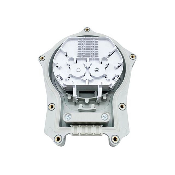
Protect fiber optic cable connections:The joint box provides physical protection for the fiber optic cable connection parts to prevent damage to the fiber optic cable caused by external environmental factors such as moisture, dust, chemical corrosion and mechanical damage. Provide a stable. Fiber optic sleeves are protective devices used for fiber optic connections. Splice protection sleeve, usually made of plastic or metal, are used to secure and protect the fusion joint between two optical fibers. Fiber Cable Joint Box is attributed to the mechanical pressure sealing joint system. Fiber Cable Joint Box is a continuous protection device for supplying optical, sealing and mechanical strength continuity between adjacent optical. The optical fiber terminal box is the terminal joint of an optical cable, one end of which is an optical cable, and the other end is a pigtail, which is equivalent to a device that splits an optical cable into a single optical fiber. The user optical cable terminal box installed on the wall, its. Fiber Optic Splice Closure is designed to protect optical fibers from debris, dirt, dust, moisture and water. As much of the fiber system is outside in a harsh environment, these fiber optic splice closures are designed to meet the tough protection requirements of fiber-optic splices. UnitekFiber. Overview Application of Optical Fiber Splice Closure/Joint Box/Joint Closure: 1. CATV environment.
[PDF]


