Learn how to install a distribution box safely and correctly. Covers wiring, placement, standards, and expert tips for a compliant setup. It takes the incoming power and safely distributes it to different. In this video, we'll walk you through the process of wiring a home distribution box with a detailed connection diagram. more Welcome to our channel! In this video. Whether you are an electrical contractor or a construction brigade, knowing how to properly and safely install distribution boxes is the basis of ensuring the safe operation of the entire system. It serves as a central hub for distributing electricity throughout a building, ensuring that power is delivered safely and efficiently to all the required locations. In modern electrical systems, cable distribution boxes (also known as electrical distribution boxes or distribution boxes) play a crucial role as the key hub for managing, distributing, and protecting circuits. Whether it is residential buildings, commercial facilities or industrial sites, the. In this guide, we will break down the key elements involved in connecting the main power supply to your home, providing a clear path for a successful setup. We will focus on the critical parts of the system, from basic components to step-by-step assembly procedures. Whether you are looking to.
[PDF]

A double switch box allows you to control two separate electrical circuits or devices from a single location. This can be useful in situations where you want to control different lights or appliances independently. Here is a step-by-step guide on how to wire a double switch box:. Connecting two electrical boxes together is a relatively simple job, but there are some important steps that must be taken to ensure it's done safely and correctly. From adding junction boxes to selecting the right wire gauge, the following steps will help guide you in installing an electrical. A double switch box, often called a double gang box, is a rectangular enclosure designed to house two electrical devices, such as two single-pole light switches. Before beginning any electrical work, safety is the. We're diving into some essential 'electrical wiring' in this video, focusing on how to properly set up an wireing a'electrical box' with a three way and single pole light switch. more Audio tracks for some languages were automatically generated. Learn more Unbelievable Trick to. This page contains wiring diagrams for two outlets in one box. Included are arrangements for 2 receptacles in one box, a switch and receptacle outlet in the same box, and 2 switches in the same box. Whether you want to control two lights from one location or two separate devices from the same switch, a double switch box is a versatile solution.
[PDF]
Learn how to install a distribution box safely and correctly. Covers wiring, placement, standards, and expert tips for a compliant setup. It takes the incoming power and safely distributes it to different. In this video, we'll walk you through the process of wiring a home distribution box with a detailed connection diagram. more Welcome to our channel! In this video. Single Phase wiring installation is the most common wiring in residential buildings. In Single Phase supply (230V in UK, EU and 120V & 240V in the US & Canada), there are two (one is Line (aka Phase, Hot or Live) and the other one is Neutral) incoming cables from the utility poles to the kWh energy. The electrical service panel, often called a breaker box, acts as the central distribution point for all electricity entering a home. An electrical panel box, also known as a breaker box or a distribution board, is a crucial component of any electrical system. It serves as a central hub for distributing electricity throughout a building, ensuring that power is delivered safely and efficiently to all the required locations. And all the switching and protective devices are installed in the distribution box. Single Phase Distribution Box generally consists of Double Pole MCBs, Single Pole MCBs, and RCCBs.
[PDF]

In this article, we'll provide step-by-step instructions on how to install a round junction box in a wall, as well as tips on safety and proper wiring techniques. First, you need to determine the. A junction box provides a code-approved place to house wire connections, whether for outlets, switches, or splices. Here's how to install one. We may be compensated if you purchase through links on our website. It acts as a central connection point for various electrical wires, allowing for the easy distribution of electricity to different fixtures and devices. A properly installed and wired junction box ensures the safety and. Nothing is more dangerous and aggravating than loose wires in a junction box. In this video you'll learn how to wire junction boxes correctly. You'll also see our favorite tools to complete this task. Thanks for watching and Have A Great Day. more. Learn how to install a junction box safely, from choosing the right box and mounting it correctly to making secure splices and following basic code-safe practices. This metal or plastic housing contains wire connections, protecting them from environmental factors and physical damage. Junction boxes are fundamental in residential and.
[PDF]

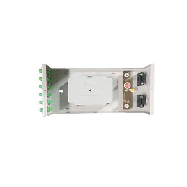
This is a simple video showing how to install a 850nm fiber optic link using SFP transceivers between 2 10 Gigabit backbone switches. Covers transceiver inst. As a leading provider of fiber optic solutions, Weunion offers a wide range of SFP-compatible products, including optical transceivers, DAC/AOC cables, LC patch cords, and MPO/MTP assemblies. This guide explores the essentials of SFP connectivity, installation best practices, and how Weunion's. These transceiver modules are hot-swappable input/output (I/O) devices that plug into 100BASE, 1000BASE and 10GBASE ports (for SFP+), which connect the module port with the fiber-optic or copper network. This document contains these sections: The SFP transceiver modules are hot-pluggable I/O. An optical module is an optoelectronic conversion device that transmits data by converting electrical signals into optical signals. Common types of optical modules include SFP, SFP+, SFP28, QSFP, QSFP28, etc. Different types of optical modules have different performance parameters such as speed. The 1310 nm WWDM solution, 10GBASE-LX4, requires the use of a mode-conditioning patch cord on multimode fiber to achieve its specified range of operating distances. more Audio tracks for some languages were automatically generated. Learn more This is a simple. One of the most widely deployed optical solutions for short-distance 10G links is the multimode SFP+ transceiver, commonly referred to as a 10GBASE-SR module.
[PDF]
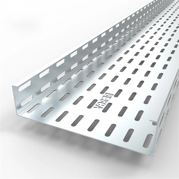
It is relatively affordable, especially when considering its durability and long lifespan. Additionally, it requires minimal maintenance, reducing ongoing costs. It is generally easy to install and can be quickly integrated into different systems or structures. Wire Mesh Cable Tray is often a cost-effective solution compared to other materials. We produce cable trays & their accessories, twists, elbows, tees, cross, reducers, etc. Our trays are designed to remain flexible offering organized solutions that helps minimize problems with full focus on safety in Bhutan. Strong Support: It holds heavy cables securely. Neat Organization: Keeps wiring systems tidy and safe. Explore and shop for the finest Wire Mesh Cable Tray online at India's leading marketplace for construction materials, industrial tools, electricals, and office equipment. brings the Cable Trays in Bhutan just for you! We, one of the well-known Cable Trays Manufacturers in Bhutan, offer top-notch trays that keep your electrical system organized and protected. Our range is customized and passes stringent quality tests, before reaching the market.
[PDF]

This video shows real on-site footage of electrical installation, demonstrating safe and standardized wiring methods used by professionals. more Learn how to wire a distribution box step by step! This video shows real on-site footage of. Connecting a distribution box involves several steps to ensure proper electrical flow. Follow this guide for a clear and safe connection process: Before starting, always ensure the main power is turned off to avoid electrical shock. Fix the box securely to the wall, ensuring it's at an accessible. An electrical panel box, also known as a breaker box or a distribution board, is a crucial component of any electrical system. It serves as a central hub for distributing electricity throughout a building, ensuring that power is delivered safely and efficiently to all the required locations. In this guide, we'll break down everything you need to know to install a distribution box correctly and confidently. Choose the right box based on environment (indoor/outdoor), load capacity, and durability. Check for proper IP/NEMA ratings and material quality. Whether you're an electrician or a DIY enthusiast, this guide will help you understand the basics of home electrical distribution. Material preparation: Prepare the required circuit breakers, wires, wiring ties and other materials, and ensure that they meet the design drawings and installation requirements. Location determination:.
[PDF]

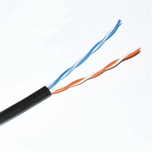
Fiber optic cables offer superior performance compared to copper cables, especially over long distances. They provide higher data transmission rates, larger bandwidths and are immune to electromagnetic interference. Fiber optic cables and copper wires are the two primary types of cables used in networks. Fiber optic cables transmit data using light waves, enabling higher. Fiber optic tends to be the more premium solution, while copper wiring is far more common, but why is that? What are the differences between these two cable types, and why might you want to pick one over the other? Here's everything you need to know about fiber vs. Copper wire is more susceptible to interference and has limited data capacity, making optical fiber the preferred choice for modern high-speed. If you're deciding between copper and fiber optic cables, it's not just a question of cost, it's about purpose, environment, and future readiness. Both have distinct strengths that can serve very different networking needs depending on your setup. Fiber optic cables provide. In today's fast-paced digital world, choosing the right network cable can significantly impact the performance, reliability, and security of your communications infrastructure. Among the most commonly used cables are copper and fiber optic cables, each offering unique advantages depending on the.
[PDF]
Welcome to our channel @Electricalgenius In this video, we'll take you through a detailed step-by-step guide on wiring a home distribution DB (Distribution Board) box. A distribution box, also known as an electrical distribution board, is a critical component in electrical systems. It serves as a central point for distributing electricity to various circuits in a building or facility. Whether you're an electrician or a DIY enthusiast, this tutorial will help you understand the fundamentals of wiring a. Distribution Board or DB is an electricity supply system or a common enclosure that distributes the electrical power feed into subcircuits. Whether in a home or an industrial facility, this box keeps your electrical setup organized, functional, and efficient. However, the key to. Circuit breaker wiring configurations involve organizing main switches, busbars, and branch breakers within a distribution box. Common configurations include single-phase for homes and three-phase for.
[PDF]

NOTE: Insert the end of a colored wire into one of the holes in a butt connector. With the wires pushed tightly against the far inside wall of the connector, squeeze the red button until it depresses. The OS-8171 Beam Splitter is designed to be used with the OS-8170 Brewster's Angle Accessory and the OS-8539 Educational Spectrophotometer System. ) In the Brewster's Angle experiment, the Beam Splitter is used with a. am Splitters/Combiners. This document describes this product line, as well as general operation guidel into two output beams t beams of equal power. The standard product is designed for use in the visible spectrum 400-700 nm wavelength). Custom Surgical Beam Splitter sends 50% of the light to the eyepieces and 50% to the smartphone camera. If you want to understand more about how beam splitter works, watch the video below. It is not necessary to. As title. in your towing vehicle manual. Be sure the hitch is installed onto the vehicle. Releasing the pin before will cause supp owards the engine faster than you can let go. This is because if a fire. Meadowlark Optics presents its VersalightTM wire grid polarizing beam splitters. Manufactured for wavelength ranges between 420 and 2600 nm, this polarizer is ideal for broadband and wide field-of-view applications. Wire grid polarizing beam splitters are manufactured out of our Versalight wire.
[PDF]

In today's video, we'll be unboxing the 9-Port Power Supply Box and demonstrating how to connect the cables to provide power to CCTV cameras. A CCTV power supply box sends power to all your cameras from one place. It helps keep things neat and makes your system easier to manage. In this guide, you'll learn how to install it step by step, choose the right type, avoid common problems, and keep your system running safely. Power supply boxes for CCTV are typically used in multi-camera installations instead of using single power adapters for each camera. The process is almost exactly the same if you. Installers of surveillance systems may simply control the power to various CCTV cameras using a CCTV power supply box, also known as a power distribution box (usually at the location of the DVR). This enables a cleaner camera installation. Surge protection can be accomplished in two ways. The power supply box is specifically used to transfer power requirements for all cameras plugged in on the system, to work. Security cameras use RG59U coax siamese wire or CAT5e networking cable to transmit video. Whether you are installing a power box for a new or existing camera system, it is important to understand how to connect cameras to a CCTV Power Supply Box. DC current is polarized meaning it has two leads, a.
[PDF]
Standards IEC 30129 and AS 30129 Telecommunications Bonding Networks for Buildings and Other Structures and Standard TIA607-E Generic Telecommunications Bonding and Grounding (Earthing) for Customer Premises provide guidance on the design and installation of the indoor grounding . Standards IEC 30129 and AS 30129 Telecommunications Bonding Networks for Buildings and Other Structures and Standard TIA607-E Generic Telecommunications Bonding and Grounding (Earthing) for Customer Premises provide guidance on the design and installation of the indoor grounding . Below is a comprehensive guide for implementing effective bonding and grounding systems in data centers. The Mesh-BN is the backbone of the bonding system, designed to ensure a uniform electrical potential across the entire data center. The whole structure consists of a metal circuit, a protect bus, and a ground wire. Network hardware is connected to PDUs and constantly. ed grounding kits shall be UL Listed, CSA Certified and RoHS compliant. Grounding strip and connectors shall be tin-plated. Grounding strip shall comply with EIA niversal mounting hole spacing and mount to standard racks and cabinets. The offering is designed with products that installers can use to make BICSI and ANSI/TIA/EIA-607 compliant installations.
[PDF]
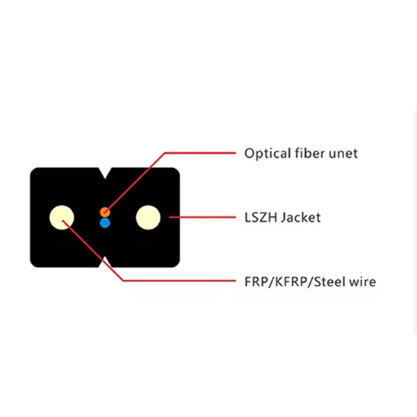
A steel messenger is a stranded steel cable that acts lashing wire. This document describes further details of messenger strand, lashing wire, and the planning and installation process. Steel messenger strand consists. Optical cable steel wire is the "invisible guard" that ensures the stable transmission of communication optical cables. It is mainly used as the reinforcing core of optical cables to provide mechanical support and protection for fragile optical fibers. In fields such as 5G networks, data centers. OPGW is primarily used by the electric utility industry, placed in the secure topmost position of the transmission line where it “shields” the all-important conductors from lightning while providing a telecommunications path for internal as well as third party communications. Optical Ground Wire is. A SWA Fiber Optic Cable, or Steel Wire Armoured Fibre Optic Cable, is a type of armored fiber cable designed to provide mechanical protection while maintaining high-speed data transmission performance. We use industry-leading equipment and processes to produce telecom wire that meets the unique demands of your applications and withstands adverse conditions. Armored fiber optic cables are constructed with a helical stainless-steel tape over a buffered fiber surrounded by a layer of aramid and stainless-steel mesh with an out jacket.
[PDF]

The maximum distance of copper is around 328 feet (100 meters), which is a far shorter range than is offered by either of the fiber optic cable types. This is because fiber optic cable is not affected by attenuation, dispersion, or EMI in the same way that copper is. Many factors decide the fiber cable distance, but the key factors include the below six aspects. Attenuation First is the attenuation of the optical fiber. For some. Fiber optic cable transmission distance is determined by two primary physical factors that affect signal quality as light travels through the fiber medium. The selection of fiber optic cables over copper wires or vice versa depends on factors such as bandwidth, distance, and cost of transmission. Fiber optic cables transmit data using light waves, enabling higher. Fiber optic cables have revolutionized modern communication networks by enabling blazing-fast data transmission across vast distances. However, fiber cable runs are not limitless. However, fiber optic cable performance. Q: Is there and electromagnetic interference with optic cables? A: The fiber is glass and the cable is plastic, neither of which are affected by electromagnetic interference. There is a cable used in electrical transmission lines called OPGW- optical power ground wire - that has fiber inside a wire.
[PDF]
This article provides a detailed guide on how to wire a generator into a breaker box along with the necessary equipment and safety precautions. Choose Transfer Method 2. Select the Generator 3. But once you have a generator sitting in your garage, the next big question is how to get that power into your home safely. In this guide, we'll walk through the basics of wiring a generator to your breaker box, step by step. We'll cover the equipment you'll need, the safety rules you can't skip. Connecting a wire generator into a breaker box is a critical process for safely powering your home during a power outage. This procedure involves integrating a portable or standby generator with your home's electrical system through the breaker box, often called the main panel. Ensure you use a double-pole breaker and interlock kit with following proper safety protocols. Unlike a standard plug, which can only handle a limited amount of power, a generator plug can handle higher voltages and currents, making it ideal for powering up. However, connecting a generator to your breaker box can be a complex and potentially dangerous task if not done properly.
[PDF]