This beginner-friendly guide will walk you through the step-by-step process of fiber optic cable installation for each method, highlighting best practices, tools, and considerations. Proper connection of fiber optic cables is essential to harness these benefits fully, as even minor errors can lead to significant performance issues like signal loss. This article will guide you through the necessary tools, materials, and methods on how to connect fiber optic cables effectively. Starting with site surveys and permissions, to installing fiber optic cable and emphasizing the process as a key stage in mastering fiber optic installation, to the careful handling of cables and high-stakes splicing, each stage is critical. Discover the exact steps, adhere to stringent safety. Single family homes, apartments, condominiums and other multi-dwelling units are increasingly wired with fiber optic cable to future-proof installations and create more reliable, higher-bandwidth and faster speed network and video infrastructures. The processes. Running fiber internally involves extending this high-speed link from the service entry point to a centralized location, such as a dedicated media closet or network rack. This DIY effort is undertaken to maximize performance, improve aesthetics, or relocate the Optical Network Terminal (ONT) to a.
[PDF]
This diagram shows how the RJ45 cable is connected to the PoE switch, allowing it to power devices such as IP phones and cameras. In this article, we will explore the wiring diagram for a PoE switch, which provides a visual representation of how the switch connects to various devices. Each device is represented by a. Do you want to set up a new computer network in your home or office? Chances are, you'll need a Poe switch wiring diagram. Not only do these diagrams provide all the information you need to install a network, but they also help make the process easier and more efficient. For those who don't know. A PoE Switch, also known as Power over Ethernet Switch, is a network device that allows users to power and connect devices such as IP cameras, VoIP phones, and wireless access points. In essence, a PoE Switch can be described as regular switch with added ability of Power over Ethernet which allows. PoE technology enables the transmission of both data and power over a single ethernet cable, simplifying network setups and eliminating the need for additional power sources. This is particularly useful in scenarios where devices like IP cameras, wireless access points, or VoIP phones need to be. Here, you can see the details, Keep the copper strips towards your face and count the pin number or pin position from left to right. The T568B also has a total of eight pins and sight different colors.
[PDF]
This section includes all PoE enabled Industrial switches available, including managed models and specific application models like vehicle or substation compliant units. Check each product page for other buying options. Shop products from small business brands sold in Amazon's store. Learn more Need help? Industrial-grade PoE switches for demanding. POE Industrial Ethernet units at Plant Technology USA make Power over Ethernet solutions even more efficient and cost effective. Not only are these de. Read more Find the best Industrial Ethernet Equipment for your project. US-based Customer Support. These rugged, fanless platforms support both Gigabit and 10/100 Mbps Ethernet and offer a selection of fixed-fiber, or SFP uplink. We provide a wide range of PoE/PoE+/PoE++ switches with up to 90 W output per port to deliver high-speed data transmission while powering high-power devices over long distances. With an industrial-grade design, our PoE switches provide surge protection of 4 kV per LAN port. Additionally, Smart PoE. In addition to transmitting network data, a PoE Switch has a built-in Power over Ethernet injector to supply up to 100W Power over Ethernet (PoE) to standards-based 802. 3bt compliant devices such as IP cameras, VoIP phones, and wireless access points. When connecting network.
[PDF]

Wiring a 3-way junction box involves connecting three separate wires: the hot wire, the traveler wire, and the neutral wire. Here is a step-by-step guide on how to wire a 3-way junction box. In a 3-way junction box, multiple wires can be joined together for the purpose of distributing power or connecting different electrical devices. Whether you are a professional electrician or a DIY enthusiast, understanding how to properly wire a 3-way junction box is essential for maintaining. In this article, we'll take a look at what you need to do in order to wire a 3-way junction box and provide you with some useful tips to make the process easier. In this comprehensive guide, we. Learn how to install a junction box safely, from choosing the right box and mounting it correctly to making secure splices and following basic code-safe practices. To install a junction box correctly, choose a box that matches the wiring method and environment, mount it securely, bring cables in. A three wire junction box is an essential component in electrical installations that allows for the connection and distribution of electrical wires. It provides a safe and convenient way to connect multiple wires, ensuring proper electrical continuity and reducing the risk of electrical hazards. We may be compensated if you purchase through links on our website. Our team is committed to delivering honest, objective, and independent reviews on home.
[PDF]
Learn how to safely wire a single-pole (one way) light switch in this beginner-friendly tutorial. Whether you're replacing an old switch or doing your first DIY electrical project, this guide will walk you through every step — no experience needed!. more. This page contains wiring diagrams for household light switches and includes: a switch loop, single-pole switches, light dimmer, and a few choices for wiring an outlet/switch combo device. That's because virtually all light switches that control 120-volt fixtures are single-pole switches. Most light switches are also single-throw, which. Summary: Fully explained wiring diagrams and photos show how to wire switches including: single switches, 3-way switches, 4-way switches, and dimmer switches. and Be Sure to Subscribe! Make sure the circuit power has been turned off, and mark the circuit breaker or fuse to indicate that work is. A distribution board or distribution box is where the main power supply is distributed to multiple loads. And all the switching and protective devices are installed in the distribution box. Single Phase Distribution Box generally consists of Double Pole MCBs, Single Pole MCBs, and RCCBs. Wiring a single light switch may seem like a daunting task, but with the right tools, a bit of patience, and this comprehensive guide, you'll be able to tackle this DIY project with confidence. Remember, while this guide provides detailed instructions, always prioritize safety and consult a.
[PDF]

This video demonstrates the process of installing a fiber optic sensor to a substrate for measuring distributed mechanical strain. The presenter explains the steps involved in preparing the surface, bonding the sensor, and applying adhesive. Fiber optic sensing (FOS) systems can provide high-fidelity distributed strain measurements in various industries such as aerospace, automotive, structural health monitoring, and civil engineering. Proper fiber optic sensor installation is crucial to obtain accurate and useful strain measurements. Trying to connect your FU Series fiber optic sensor head to the FS-N40 Series fiber optic sen. more Learn more via the catalog: https://www. It is divided into communication supplies and industrial supplies, here we refer to the industrial fiber optic sensor. The presenter explains the. Optical fiber couplers for various LEDs and light sensors are commercially available, but you can skip the connector and simply connect silica and plastic fibers directly to LEDs and sensors. For the examples described here, I used LEDs encapsulated in standard 5mm clear epoxy packages, and. This Application Note is intended to guide users of Luna's High Definition Fiber Optic Sensing (HD-FOS) system (the ODiSI) through the simple process of mounting a fiber sensor onto the surface of a test article.
[PDF]
In this blog, we will explore the step-by-step process of using a beamsplitter cube effectively, along with some common applications that benefit from this powerful optical tool. Step-by-Step Guide on Using a Beamsplitter Cube. 📦 For purchasing, use the RP Photonics Buyer's Guide for beam splitters. It provides an expert-curated supplier directory, buyer-focused technical background information, and structured selection criteria to support professional procurement decisions. What are Beam Splitters? A beam splitter (or. An Optical Beamsplitter is an optic or optical device that is used to split a beam of light in two. Newport offers a wide variety of Beamsplitters in various shapes. It is a crucial part of many optical experimental and measurement systems, such as interferometers, also finding widespread application in fibre optic telecommunications. One beam is typically reflected while the other is transmitted. The ratio of reflected to transmitted light can vary based on the design of the beam splitter. Our plate beamsplitters have a coated front surface that determines the beam splitting ratio while the back surface is wedged and AR coated in order to minimize ghosting and interference effects.
[PDF]
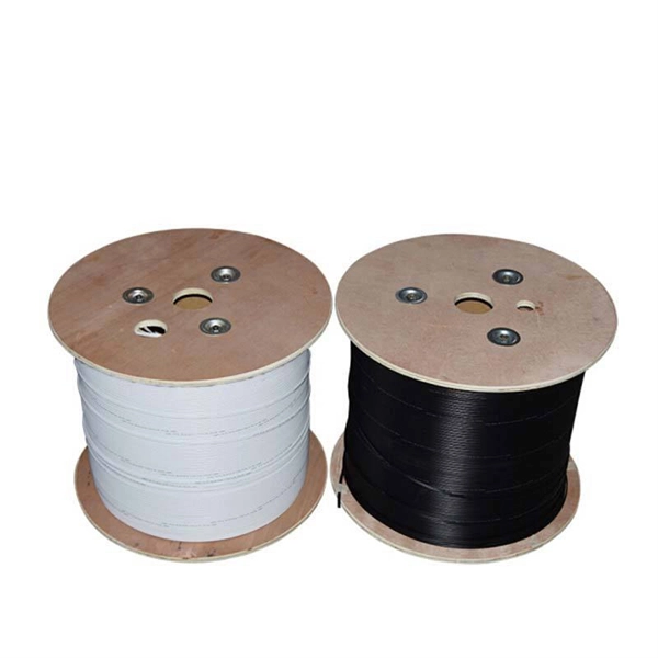
This article will provide an in-depth analysis of outdoor cable types, key selection criteria, core installation steps, critical precautions, as well as subsequent testing and maintenance guidelines, helping you build a robust and durable outdoor optical communication link. Therefore, understanding the characteristics of outdoor fiber optic cables and mastering proper installation methods is crucial. Plan your outdoor fiber installation carefully by surveying the site, choosing the right cable type, and following FOA and OSP standards to ensure reliability. In this video, we'll walk you through the process of establishing a robust outdoor fiber connectivity solution. Follow our guide and establish a r. more Welcome to. Running a cable through an exterior wall can be a daunting task for many homeowners, but with the right tools and techniques, it can be done efficiently and safely. With the increasing demand for high-speed internet and reliable networking, it's essential to know how to properly install CAT 6 cables outdoors. In this article, we'll take you.
[PDF]

Welcome to our channel! In this video, we'll walk you through the process of wiring a home distribution box with a detailed connection diagram. Whether you're an electrician or a DIY enthusiast, this guide will help you understand the basics of home electrical. This guide provides step-by-step instructions for connecting a distribution box and highlights key factors to consider during installation. What Is a Distribution Box? A distribution box, also known as an electrical distribution board, is a critical component in electrical systems. more Welcome to our. Start by positioning the control panel within 30 feet of both the generator and the main service box. This ensures minimal voltage drop and straightforward conduit routing. Connect the neutral and ground conductors to their. A manual transfer switch is installed next to the main service panel to override the normal electrical service with power from a backup generator during a power outage. Very few homeowners can afford or consider it necessary to supply power to all of the homes electrical devices, fixtures and appliances in the event of a power.
[PDF]

How to hardwire a Self-Regulating heat cable into a junction box, with a tutorial of the final end seal. First thing, get the sealing ring and connect it onto the connector body. Make sure it gets onto the very e. Safety comes first, and clear info makes it doable. Know Your. We'll show you how to size the heater, run a new, safe 240-volt circuit and install a programmable thermostat. Most homes have sufficient capacity for the new circuit in the service. If you're working with heating cables, understanding how to connect them safely and efficiently is crucial. In this guide, we'll break down the steps in simple terms. Whether you're a DIY enthusiast or a professional, this article is here to help. Stay safe and ensure proper installation with these. I need help wiring an electric furnace with heat elements. I ran number 6 wire with ground from my 100 amp service box where I installed a 60amp double pole breaker. The furnace comes with an other set of breakers one 60amp and one. A distribution board or distribution box is where the main power supply is distributed to multiple loads. Single Phase Distribution Box generally consists of Double Pole MCBs, Single Pole MCBs, and RCCBs.
[PDF]

This guide provides a complete framework for understanding, identifying, and planning MPO connector gender in data center environments. Visually, male and female MPO connectors are easy to distinguish: male connectors feature two alignment pins (PIN pins), while female connectors have corresponding holes instead of pins. An MPO connection is made between a male and female connector to make sure that there is proper alignment. Interfaces on active MPO equipment, such as transceivers are usually male, so any MPO trunk cable. In modern data centers and high-density fiber optic networks, MPO (Multi-Fiber Push-On) connectors have become an essential solution for achieving fast, reliable, and scalable connectivity. You will discover the physical distinctions between male and female connectors and how to develop a gender strategy for your infrastructure, which gender connects. Whether you're supporting parallel optics like 100G SR4 or densifying an optical distribution frame (ODF), MPO is now a cornerstone of network design. This article explains: And a practical checklist to design MPO systems that scale cleanly. If you only remember one thing: MPO is a multi-fiber. In MPO and MTP fiber connector systems, Male vs Female and Pin vs No-Pin describe the same core engineering attribute: the presence or absence of alignment pins on the MT ferrule. Unlike single-fiber connectors such as LC or SC, this distinction is not optional terminology but a mandatory.
[PDF]
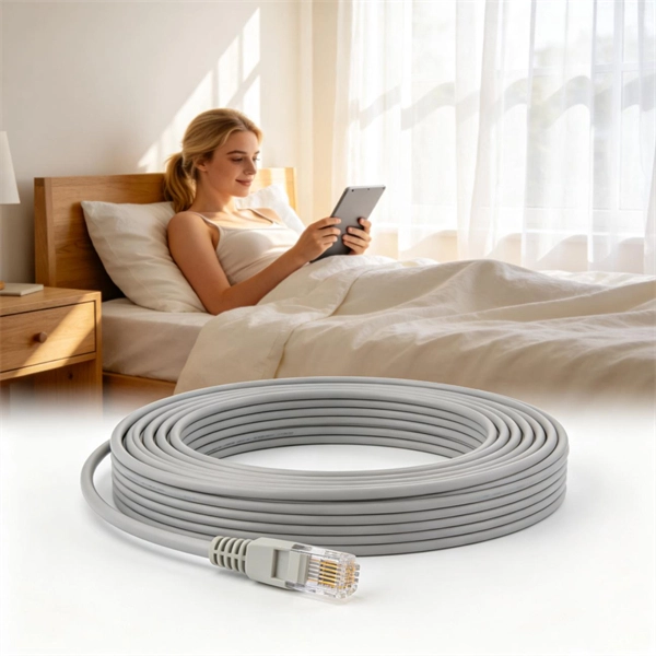
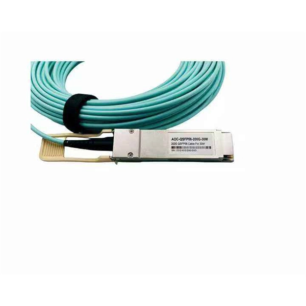
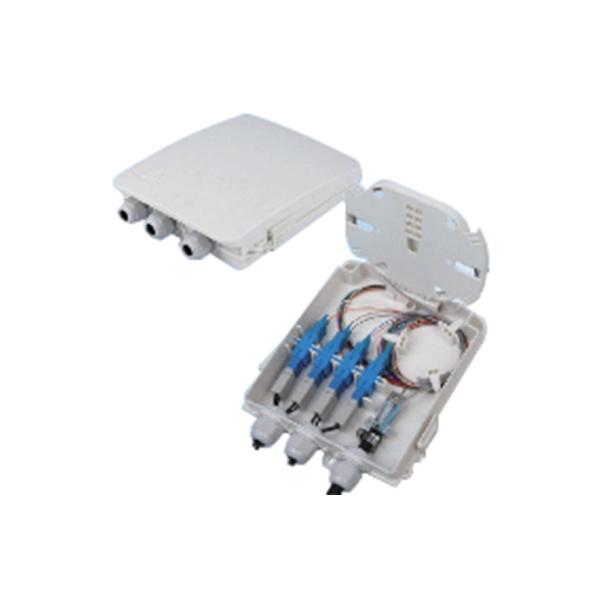
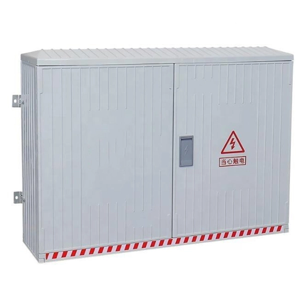
Step1 : Identify the optical cabinet and network operating center, and find the fiber optic splitter. Step 5: Patching from the splitter port to the user. Fiber optic patch cords must be installed correctly to ensure best network performance, reduce signal loss, and protect the sensitive fibers. Whether you're connecting a data center, a corporate network, or a high-density fiber infrastructure, correct installation methods are essential. Yingda. You can put in a fibre patch cord at home. You just need to follow easy steps and be careful. Planning helps you pick the right cord for your network. Be gentle when you handle the cord. Fibre patch cords last longer and are tougher than. This article will guide you through the necessary tools, materials, and methods on how to connect fiber optic cables effectively, ensuring you achieve optimal performance from your fiber optic network. Have a network installation project? Fiber Optic Cables: The primary medium for your connections. NS Comm provides enterprise-grade fiber optic patch cables engineered for maximum reliability and low-loss performance. However, proper installation techniques are essential to unlock their full potential. This guide will help you understand fiber construction, installation steps, real attenuation. Correct patch-cord installation is essential for maintaining low insertion loss, stable return loss, and long-term reliability in both indoor and outdoor fiber networks.
[PDF]

NOTE: Insert the end of a colored wire into one of the holes in a butt connector. With the wires pushed tightly against the far inside wall of the connector, squeeze the red button until it depresses. The OS-8171 Beam Splitter is designed to be used with the OS-8170 Brewster's Angle Accessory and the OS-8539 Educational Spectrophotometer System. ) In the Brewster's Angle experiment, the Beam Splitter is used with a. am Splitters/Combiners. This document describes this product line, as well as general operation guidel into two output beams t beams of equal power. The standard product is designed for use in the visible spectrum 400-700 nm wavelength). Custom Surgical Beam Splitter sends 50% of the light to the eyepieces and 50% to the smartphone camera. If you want to understand more about how beam splitter works, watch the video below. It is not necessary to. As title. in your towing vehicle manual. Be sure the hitch is installed onto the vehicle. Releasing the pin before will cause supp owards the engine faster than you can let go. This is because if a fire. Meadowlark Optics presents its VersalightTM wire grid polarizing beam splitters. Manufactured for wavelength ranges between 420 and 2600 nm, this polarizer is ideal for broadband and wide field-of-view applications. Wire grid polarizing beam splitters are manufactured out of our Versalight wire.
[PDF]

This guide delves into the structure and working principle of fiber optic connectors and outlines the critical steps for creating a successful connection. Proper connection of fiber optic cables is essential to harness these benefits fully, as even minor errors can lead to significant performance issues like signal loss. This article will guide you through the necessary tools, materials, and methods on how to connect fiber optic cables effectively. This guide will explain the entire set of activities involved in installing Fiber optic cable contractors -from the early planning stage right through testing-for facility managers, IT teams, and low-voltage contractors to build high-performance networks safely and efficiently. The processes. However, working with fiber requires specialized skills and equipment to connect cables properly. This guide will walk you through the complete process of connecting fiber optic cable. Before connecting any fiber cable, you need to assemble the proper preparation tools: With the right tools in. The Fiber Optic Association, Inc. (FOA) was founded in 1995 to help develop the workforce to build the fiber optic networks to support a rapid expansion in communications and the Internet.
[PDF]

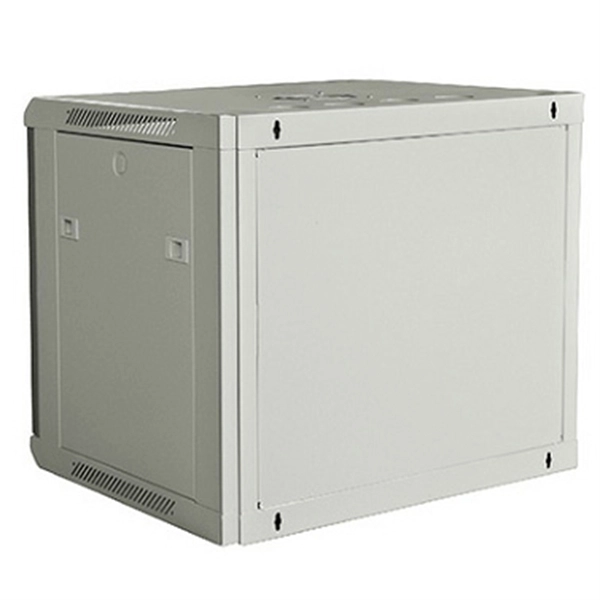
In this guide, you will learn how to interpret network diagrams like a pro, from symbols and scope to segmentation, dependencies, troubleshooting, and security clues. A rack elevation diagram is a visual representation of the equipment and components contained within a rack in a data center or server room. It provides a clear overview of the physical layout of the rack, including the placement and positioning of servers, switches, storage devices, and other. Learn how to read and interpret network diagrams effectively to troubleshoot, validate security, and plan network changes with confidence. Have you ever opened a network diagram and felt like you were staring at a subway map with no station names? That is a common problem, even for experienced IT. Network cabinet cabling describes the structured connection and arrangement of all IT components in a server rack. The aim is a secure, maintainable and scalable operation of the network environment. The amount. A standard operating procedure, or SOP, is a set of step-by-step instructions compiled by an organization to help workers carry out complex routine operations. Work instructions should be very detailed on "how" to accomplish a specific job, task or assignment. It helps teams understand network architecture, data flow, and dependencies, making it easier to design infrastructure, troubleshoot issues, and plan.
[PDF]