Run the following command to view detailed optical module information on the device interface: display transceiver interface <interface-type> <interface-number> verbose The command output is divided into two parts:. Run the following command to view detailed optical module information on the device interface: display transceiver interface <interface-type> <interface-number> verbose The command output is divided into two parts:. When the optical module on an interface is faulty, you can run the display commands to view information about the optical module. Related Information Video Identify a Huawei-Certified Optical Module Run the display transceiver [ interface interface-type interface-number | slot slot-id ] [ verbose ]. During use, reading optical module information helps understand its real-time operating status, enabling faster troubleshooting of link abnormalities. The following uses the Moduletek SFP-10G-LR module connected to a Huawei S6700 switch as an example to introduce how to read information of the. See the interface module via the optical display command information, including general information of the optical module, manufacturing information, and alarm information. If it is not a Huawei-certified optical module, replace it with a Huawei-certified optical module. If the optical module is installed on a GE port, run the display interfaceGigabitEthernet x/x/x command to view port information when the optical module.
[PDF]

As a leading manufacturer and supplier of fiber optic components, we consistently provide high-quality fiber optic components, fiber optic active connectors, optical splitters, fiber optic adapters, fiber optic cables and other products. Huijue Group's energy storage solutions (30 kWh to 30 MWh) cover cost management, backup power, and microgrids. To cope with the problem of no or difficult grid access for base stations, and in line with the policy trend of energy saving and emission reduction, Huijue Group has launched an. Founded in 2002, Huijue Group is a high-tech service provider integrating intelligent energy storage equipment and computer intelligent network communication system integration and application. Huijue Network's products are exported to Europe, North America, Southeast Asia and other countries and. Shanghai Technology R&D Center was established, opening the mode of independent R&D and innovation Self-owned brand products enter the radio and television and operator markets Established more than 20 offices in China. The group owns 6 wholly-owned subsidiaries and 4 major production bases located in Shanghai, Yangzhou, Haian, and. Premier producer of solar energy storage solutions & Site-specific Products, excelling in quality & efficiency.
[PDF]

This article compares typical cost ranges across speeds and transceiver types, explains why prices vary, and gives practical guidance for choosing the right optics for a given budget and performance requirement. This article helps network architects and procurement teams run a practical cost analysis for implementing Open RAN using pluggable optical modules across fronthaul and midhaul. All price bands below are market-observed ranges (OEM-branded vs. As per our latest research, the 25G Fronthaul Optical Module market size reached USD 1. 42 billion globally in 2024, demonstrating robust growth driven by the accelerating deployment of 5G wireless networks and expanding data center infrastructure. The market is projected to grow at a CAGR of 18. 7% from 2025 to 2033, reaching a forecasted value of USD 4. 47. The 5G fronthaul optical transceiver modules market is experiencing rapid evolution driven by the global rollout of 5G networks. These modules form the backbone of high-capacity, low-latency communication infrastructure essential for 5G deployment.
[PDF]

In this tutorial video, we will show you step-by-step how to safely and effectively remove an optocoupler from a circuit board using desoldering wick. We will walk you through the tools you will need, the proper technique for using the desoldering wick, and the precautions to take to av. more In. Whether you're replacing a faulty component, salvaging parts from an old board, or correcting a soldering mistake, knowing how to desolder effectively is essential. This guide will walk you through the tools, techniques, and best practices for desoldering components from a circuit board safely and. Desoldering is a process that removes the solder and components from a printed circuit board or any other type of electronic assembly. This is a meticulous process and it can easily damage the board, or the components, if not properly done. Thus, it is important to know how to desolder properly. If you're desoldering a battery from a circuit board, use flush cutters to cut each wire one-at-a-time to isolate the battery before you desolder the wires. Whenever possible, create an indirect path by soldering connectors onto the battery and the circuit board. This reduces the chance of an. Sorry, an unexpected error has occurred. Why Publish? The Ultimate Guide to Desoldering: From using desoldering irons to sketchily knocking breadboard components off on the side of a table, there are tons of ways to remove components from a circuit board.
[PDF]

When you connect two 1000BASE-T switches with SFP ports to achieve Gigabit Ethernet, there are two methods: through standard Ethernet cable plugged into the built-in Ethernet ports of each switch, or use the SFP ports with a copper SFP module. 🎥 In this video, I show you how to connect two different branded switches using SFP modules and fiber optic cables. Whether you're using Cisco, Planet, TP-Link, D-Link, Ubiquiti, or any other brand — the key is understanding SFP compatibility. Before moving ahead, let us discuss some basics about standard Ethernet cables and 1000BASE-T (IEEE 802. Network topology refers to the way in which the links and nodes of a network are arranged in relation to each other. What Is a 10Gb SFP Module? A 10Gb SFP (Small Form-factor Pluggable) module is a compact, hot-swappable transceiver used to establish high-speed fiber. Did you swap one of the fiber connectors at one of the endpoints? Meaning, take off the housing of the fiber connector, and swap a and b. You'll find SFP / SFP+ specs on the datasheets for the switches. They're free to view and download from Cisco. Cisco also publish a GBIC /. Most modern fiber-enabled network switches require an SFP transceiver module featuring a duplex (two strand) multimode OM3 or duplex single mode OS2 connection with LC connectors. Direct attach cables with pre-terminated SFP connections may also be used. Download the Application PDF SFP transceiver.
[PDF]
Run the display device esn command to view the chassis serial number. The command format may vary depending on the. This document describes how to obtain the serial numbers of S series switches running V600. The serial numbers of devices are necessary for network construction and device maintenance. GigabitEthernet1/0/2 FINISAR CORP. FTLF1619P1BCxxxx PR7xxxx 2014-02-21 NO GigabitEthernet1/0/10. This topic describes the encapsulation types of optical modules on WDM products Small form-factor pluggable (SFP) optical modules are compact, hot-swappable, low-speed optical modules. They comply with the specifications defined in the multi-source agreement (MSA) and support synchronous optical. Here are the common commands to use to display hardware-related information on Huawei Routers. The inventory information such as serial number, product code,optical module,device, power,voltage,temperature,fan, CPU and memory are very important on operation and troubleshooting purposes. Your email. ALL DIMMING BALLASTS TO BE LUTRON ECOSYSTEM, ECOSYSTEM H-SERIES, OR HI-LUME 3D TYPE. TO CONFIRM ALL CIRCUITING REQUIREMENTS. ARCHITECT TO VERIFY QUANTITY, LOCATION & FINISH OF ALL CONTROLS. This paper presents an Echo State Network (ESN)-Driven joint decision strategy for a configurable security Non-Orthogonal Multiple Access (NOMA) optical communication system. To address security vulnerabilities, a configurable key iteration scheme is introduced, achieving temporal interleaving of.
[PDF]
There are a total of 379 Optical Products Manufacturers in Africa as of April 01, 2026. (Google Earth) file formats. 98% increase from 2023. 75%. Promoted | NEC XON and Smartoptics are introducing a new era of pluggable optical solutions for Africa. For years, African. This section provides a list of the top 10 Optical Module manufacturers, Website links, company profile, locations is provided for each company. Also provides a detailed product description of the Optical Module, including product introduction, history, purpose, principle, characteristics, types. As specialized fiber optic transceivers manufacturer, Star Computer Limited is located in Johannesbur, South Africa. The company was founded in 1999, at first we mainly made cable assemblies, later we expanded our business to various kinds of fiber optic transceivers, our transceiver products types. The rapid development of AIGC has promoted the demand for 800G optical modules, and the entire industrial chain involving optical components, optical modules, and optical communication equipment is expected to fully benefit. To help you choose the best partner, this article will analyze and. Avago Technologies (now part of Broadcom Inc. ) is a global leader in high-performance optical and networking components. Their family of Small Form Factor Pluggable (SFP) LC optical transceivers is designed to deliver reliable, scalable, and energy-efficient connectivity across enterprise, data.
[PDF]

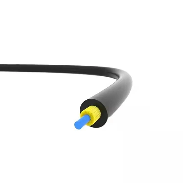
BBU end can be connected to CWDM coarse wavelength division multiplexer through CWDM color optical module and OS2 single mode optical fiber patch cord, and then transmitted to CWDM coarse wavelength division multiplexer with one or two optical fibers. The operation of base stations requires a large number of optical modules for interconnection between devices, and we will talk about the application of optical modules in mobile communication base stations. Communication base station is composed of machine room, base station, antenna, feeder. The base station can be divided into two modules: the RRU for transmitting signals and the BBU for processing signals. The BBU is small and exquisite, with low power consumption, while the RRU is large and has high power consumption. In 4G networks, the optical modules used to connect BBU and RRU are mainly gigabit to 10Gbit optical modules. In modern server racks, the wrong optical choice can silently tax performance: queues grow, link training becomes flaky, and operators end up swapping modules mid-quarter. In 5G networks, CPRI is also upgraded to eCPRI. Currently, 5G of the bearer network mainly uses 25Gbps optical.
[PDF]

As illustrated in typical SFP internal structure diagrams, the module's core components include an optical transmitter assembly (TOSA), laser driver, optical receiver assembly (ROSA)—some high-sensitivity modules (like L16. 2) use APD receivers, which require an additional booster. The optical module serves as a crucial component in optical fiber communication systems, operating at the physical layer, which is the lowest layer in the OSI model. Its primary function is to achieve optoelectronic conversion by converting electrical signals into optical signals and vice versa. Among various optical module form factors, SFP (Small Form-Factor Pluggable). The function of the optical module is to carry out the photoelectric and electro-optic conversion. In this article, ETU-LINK will introduce to you what are the core components of the optical module? 1. TOSA: Its main function is to convert electrical signals to optical. the embodiments of the present applicationprovide an optical emission module, an emission device, a detection device and a terminal, which can improve the energy density of a light spot formed by an emission light beam and improve the integration of the device. an embodiment of the present.
[PDF]

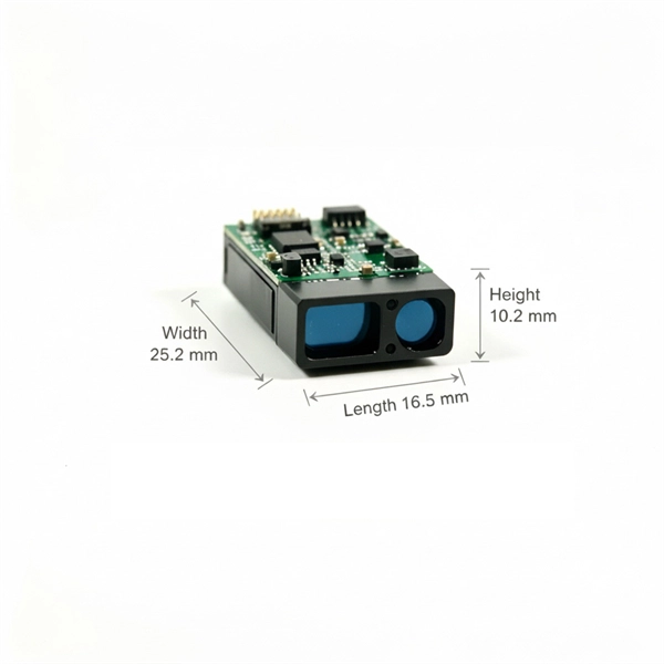
It emits a stable red light driven by a constant current source, which is coupled into the optical fiber through an interface to perform fiber fault detection functions. These include checking fiber connectivity and locating faults such as fiber breaks and bends. The B5 Rechargeable Red Light Pen is a professional 650nm visual fault locator designed for fiber optic network maintenance, installation, and troubleshooting. Its advanced rotary automatic lift laser head ensures smooth operation, while the integrated LED lighting improves visibility in low-light. Luxbond LBTEK Fiber Optic Red Light Pen (also known as a pen-style visual fault locator or fiber optic fault detector) uses a 650 nm semiconductor laser as the light source. Note: Meant for use with polished, terminated fiber cables. Always insert and remove the fiber connector without bending the connector to avoid breaking. The RPEN-210 is a necessity tool that should not be missing from any fiber plant manager or fiber optic installing technician. The Visual Fault Locator (VFL) Pen has a visible red light source centered on 650nm. Tool sends visible light over a fiber strand with a 10mW power, good enough to reach. ● Practical Design: Small size and lightweight, pen-type design with pouch make it portable. Design with a stainless steel head and aluminum body to prevent crash and dust, the case ground design prevents ESD damage efficiently Temp. Only registered users can write questions.
[PDF]
A passive optical network (PON) is a point-to-multipoint fiber network architecture that uses optical splitters to deliver high-bandwidth services from a single fiber to multiple end users without requiring active electronics in the field. While there are many subtle differences, a clear distinction between active optical networking and PON topology is PON's use of a. A passive optical network (PON) is a fiber-optic telecommunications network that uses only unpowered devices to carry signals, as opposed to electronic equipment. In practice, PONs are typically used for the last mile between Internet service providers (ISP) and their customers. In this use, a PON. A passive optical network sends data as light through fiber cables. You get internet, TV, and phone services with fewer cables and no powered splitters between you and your provider. What equipment do you need for PON at home? You need an optical network unit (ONU) at your home. By eliminating powered components between the service. Technology drives the broader adoption of passive optical LAN (also known as a passive optical local area network) across various sectors. Not having a long history as a passive optical network (PON), it is a better replacement for copper-based LANs in local area networks. This article covers every.
[PDF]
The CFP, short for C form-factor pluggable, is a multi-source agreement to define the form-factor of the optical transceiver for high-speed digital signal transmission. CFP transceivers are defined by CFP MSA to enable 40 Gb/s, 100 Gb/s and 400 Gb/s applications. The c stands for the Latin letter C used to express the number 100 (centum), since. What is a CFP optical module? Is it still relevant in 2026? And when should you choose it over newer alternatives? This guide is designed to answer those questions with clarity and technical depth. In this comprehensive article, we will delve into the world of CFP optical transceiver modules, exploring their. What is CFP Modules? Complete Guide to Standards, Variants, Comparisons, and Applications What is CFP Modules? Complete Guide to Standards, Variants, Comparisons, and Applications What is CFP Modules? Complete Guide to Standards, Variants, Comparisons, and Applications In the era of cloud. This article breaks down the key differences between CFP, CFP2, CFP4, and CFP8 optical transceivers commonly used in fiber optic networks. Figure 1: Dimensions of CFP, CFP2, CFP4, and CFP8 The table below summarizes the specifications of each form factor: 24 W (Max. ) In essence, the progression.
[PDF]

Continuous-wave operation (cw operation): The laser is continuously pumped and emits light continuously, either on a single resonator mode (→ single-frequency operation) or on multiple modes (see also: single-mode operation). How do optical. EML stands for Externally Modulated Laser (corrected from "External Modulated Laser"). Its basic principle is to supply a constant current to the laser diode, ensuring the LD emits continuous, stable light. An external electro-absorption modulator (EAM) then adjusts light transmittance to generate. A wavelength swept light source emits laser light with a continuously sweeping wavelength. It is suitable for shape measurement and displacement measurement utilizing OFDR (Optical Frequency Domain Reflectometry), an optical sensing method using the coherence of laser light. The transmitting interface inputs electrical signals of a certain bit rate, which are then processed by internal driver chips. Subsequently, the driver semiconductor laser. Industry pundits have recently speculated that demand for 100G/400G switches may take off in 2019, prompting optical transceiver module vendors to sample data center switches with high data transmission rates earlier than expected. As data center operators accelerate upgrades in preparation for 5G.
[PDF]
These networks rely on optical fibers, which are thin strands of glass or plastic that carry light signals. The ONU serves as the termination point of a fiber-optic network, converting the optical signals back into electrical signals for distribution to end-user devices. A GEPON system usually consists of an OLT (Optical Line Terminal) at the service provider's central office and multiple ONU (Optical Network Units) or ONT (Optical Network Terminals) close to the end user as optical splitters. In addition, the transmission between OLT and ONU/ONT adopts an optical. In the realm of Fiber-to-the-Home (FTTH) and other FTTx architectures, the Optical Network Unit (ONU) is a critical piece of customer-premises equipment (CPE). The primary function of an. ONU stands for Optical Network Unit. Think of it as. ONU (Optical Network Unit) plays a crucial role in modern telecommunications, enabling seamless connectivity and high-speed data transmission across fiber optic networks. As global demand for Fiber-to-the-Home (FTTH) expands, ONUs have become essential for delivering reliable broadband to homes. As an essential node in Passive Optical Networks (PON), the ONU not only handles the conversion between optical and electrical signals but also supports various services such as data, IPTV, and voice. This article will provide a detailed explanation of the working principles of ONUs and their.
[PDF]
It exhibits 3 RF ports including 3 switches. It includes a 6-bit phase shifter, a 6-bit attenuator, and switches. It covers the frequency range from 8 to 12 GHz and provide 5. 8 dB of gain at 10 GHz. One of the biggest IT/Electronic importers in Cambodia. We have partnerships with many big name brands like Dell, Lenovo, and many more. Copyright © 2026 ICE Electronics. We have partnerships with many big name brands like. Fiber optic transceiver modules are fiber cable adaptive housings that contain a light source for transmitting data via fiber optic cable as well as a photodiode for receiving fiber optic data. Mounting options include pluggable CXP, QSFP, SFF, SFP, and XFP, surface or through-hole, CFP, 1x9 SC. Estimator and calculate data for freight forwarding services. Sea freight calculator. Estimate for shipping a container, 20ft or 40ft. Calculate freight and box quantity container shipping cargo. External HDD Memory Speaker Network Used Computer Meeting Conference RACK News Photo Copy Contact Us Visitor Number 02732447 Address: #156BE, St. 63 (Trasak Phaem), Sang kat Chactomok, Khan Daun Penh, Phnom Penh Tel: (23)220 345/ 221 945,012 93 63 02/015 999 157/011 999 157/093 639 888 / E-mail:. The CGY2170YHV/C1 is a high performance GaAs MMIC T/R 6-bit core chip operating in X-band. It covers the. Maximize Budget, Ensure Timely Delivery Join An IT Community Designed to Foster Business Growth. 1000BASE-LX/LH SFP transceiver module, MMF/SMF, 1310nm, DOM.
[PDF]