This report describes a set of five field evaluations conducted by Pacific Northwest National Laboratory (PNNL) and DesignLights Consortium for U. Department of Energy, between November 2015 and September 2017, to demonstrate the potential energy-savings capability of advanced . Lighting systems define the difference between a toy grade machine and a professional-grade scale crawler. Choosing the right controller dictates how that light behaves, moving beyond simple on-off switches into the realm of true scale realism. Integrating these systems transforms a static rig into. What Defines a Great Lighting Control System in 2025? 1. Lutron (Vive & Quantum): The Scalable Market Leader 2. DALI (Digital Addressable Lighting Interface): The Open Protocol Standard 3. Crestron: The King of High-End Integration 4. Casambi: The Leader in Bluetooth Mesh Wireless Control 5. PoE. These systems provide a consolidated method for managing all of your home's lights using a single app or device. However, choosing from the wide range of available options might be challenging. To assist you in making a wise choice, we have put together a guide to the top home lighting control. re being properly set up and tested for the Program Administrators (PAs). These criteria will ease the decision-making around the appropriate savings factors and incentive levels that projects can claim. By combining technical parameters with hands-on project experience, it supports designers.
[PDF]

This guide will walk you through the process of checking photo sensors using a multimeter, covering various types of photo sensors, the necessary tools and safety precautions, and the specific measurement techniques involved. Knowing how to effectively use a multimeter to test photo sensors can save you time, money, and frustration when dealing with malfunctioning devices. more What is a Voltage Divider? | What is a Voltage. Before replacing the sensor or fixture, it's efficient testing it first, With a few tools and a step-by-step process you can find whether your outdoor lighting control system is working as intended or if the problem lies elsewhere. In this complete guide from Lead-Top, a global leader in photocell. In this blog post, we explain step-by-step how to troubleshoot a sensor with a digital multimeter (DMM). Here are the steps: Troubleshooting a sensor measurement failure requires mechanical tools to uncover the protective shields or components so you can reach the sensor in question. Always follow the manufacturer's instructions for the sensor and multimeter. Ensure the sensor is properly connected to the multimeter and. A multimeter is an indispensable diagnostic tool for anyone working with electronics, electrical systems, or indeed, sensors. It's a versatile device capable of measuring voltage, current, and resistance, providing crucial insights into the health and functionality of electrical circuits and.
[PDF]

Santa Cruz de la Sierra has emerged as the primary industrial engine of Bolivia, accounting for a significant portion of the nation's GDP through agribusiness, heavy manufacturing, and energy sectors. As these industries transition from traditional mechanical fabrication to high-precision digital. Fiber optic sensors manufacturer offering solutions for Oil & Gas, Aerospace & Defense, civil engineering, geotechnical and other industries. Opsens Solutions, a divisions of Opsens Inc., develops, manufactures and supplies a wide range of. As these sectors transition toward Industry 4. 0, the demand for high-precision joining. The industrial landscape of Santa Cruz de la Sierra, Bolivia, serves as a critical node for South American manufacturing, particularly within the sectors of heavy machinery fabrication, agricultural equipment, and structural steel production. As the region transitions from traditional agro-industrial processing toward high-tech metal fabrication and aerospace components.
[PDF]

This video demonstrates the process of installing a fiber optic sensor to a substrate for measuring distributed mechanical strain. The presenter explains the steps involved in preparing the surface, bonding the sensor, and applying adhesive. Fiber optic sensing (FOS) systems can provide high-fidelity distributed strain measurements in various industries such as aerospace, automotive, structural health monitoring, and civil engineering. Proper fiber optic sensor installation is crucial to obtain accurate and useful strain measurements. Trying to connect your FU Series fiber optic sensor head to the FS-N40 Series fiber optic sen. more Learn more via the catalog: https://www. It is divided into communication supplies and industrial supplies, here we refer to the industrial fiber optic sensor. The presenter explains the. Optical fiber couplers for various LEDs and light sensors are commercially available, but you can skip the connector and simply connect silica and plastic fibers directly to LEDs and sensors. For the examples described here, I used LEDs encapsulated in standard 5mm clear epoxy packages, and. This Application Note is intended to guide users of Luna's High Definition Fiber Optic Sensing (HD-FOS) system (the ODiSI) through the simple process of mounting a fiber sensor onto the surface of a test article.
[PDF]
High-definition strain sensing based on the Rayleigh backscatter delivers a virtually continuous line of strain measurements with sub-millimeter spatial resolution, employing very small lightweight optic.
[PDF]
With the increasing of water pollution problems, detection of heavy metal ion concentration in water environment becomes significant. Optical fiber sensor, with its particular advantages of small-size, anti-e.
[PDF]
A compact fiber Bragg grating (FBG)-based strain sensor has been developed by embedding an FBG inside a 3D-printed structure, allowing the comparison of FBG responses across different filaments such a.
[PDF]
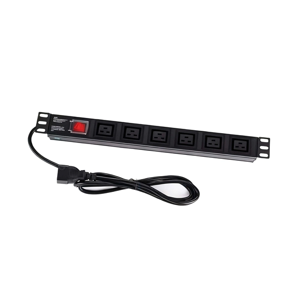
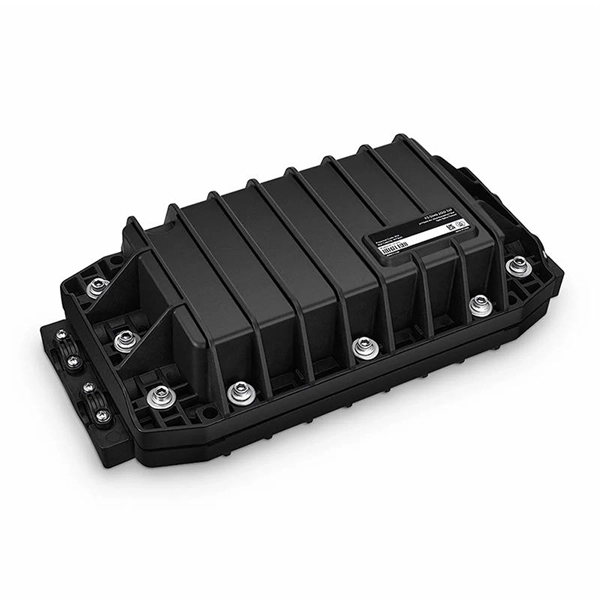
At Multilink, we offer traffic power solutions to keep traffic signals, camera equipment, illuminated street signs and other tech up and running. Power traffic signals, camera equipment, lighting and other t.
[PDF]
This article explores the different types of Fiber Optic Sensors, their working principles, and various applications. while constructing a complete Fiber Optic Link (Central Office to Outside Plant to Customer Premise). Hence, this course will. The fiber optic sensor has an optical fiber connected to a light source to allow for detection in tight spaces or where a small profile is beneficial. The optical fiber consists of the core and the cladding, which have different refractive indexes. This is a very interesting and also well-known topic in the research field. Fiber optic sensors play a key role in developing the communication system to sense & measure the change within. Imagine a world where the Internet doesn't just connect but senses —detecting earthquakes, monitoring battery health, or safeguarding critical infrastructure. This is the power of fiber optic sensing, a technology that transforms ordinary optical fibers into the digital world's sensory network. We'll delve into Intrinsic, Extrinsic, and Hybrid fiber optic sensors, explaining how they function. A sensor is a device that measures a physical quantity and converts it into a. Konnexx is an industry leader in Jamaica and the Caribbean, providing world class services in the telecommunication and broadband industries offering a wide range of telecommunication support services for commercial and private entities. We offer comprehensive solution for businesses interested in.
[PDF]

The core measurement procedure follows five steps: Turn on the meter and let it warm up. Most meters need a brief stabilization period before readings are reliable. Check your model's manual, but a minute or two is typical. Set the wavelength to match your light source. Fiber loss is the difference between the power when light is coupled from the transmitting end to the fiber and the power when the light reaches the receiving end. Generally speaking, when measuring the. An optical power meter measures the strength of light traveling through a fiber optic cable, giving you a reading in dBm (decibels relative to one milliwatt). The basic process is straightforward: turn the meter on, set it to the correct wavelength, clean your connectors, plug in, and read the. A power meter and light source are essential test tools that work in tandem to measure fiber optic cable loss and evaluate the quality of optical links. They provide the data necessary to quantify signal loss and pinpoint issues that could impact network performance. Here's how they work: A power. You measure optical power in dBm or insertion loss in dB. Verify light travels from transmitter to receiver. We'll give you the basic information you need and provide some printable references.
[PDF]
This article will deeply explore the unique charm of optical circulators from five aspects: the forefront of technological innovation, efficient cyclic transmission, wide application fields, excellent and stable performance, and future development prospects. Frontier of. An Optical Circulator is a non-reciprocal device that routes light from one port to the next, in a unidirectional manner. This unique device has broad applications in many fields, from optical telecommunications to fiber-optic sensor systems. They are crucial components in modern optics and photonics, enabling the efficient routing of optical signals. The basic principle of an optical. The evolution of optical circulators can be traced back to the advancements in fiber optics technology during the late 20th century, which necessitated the development of devices capable of managing complex light pathways. They are technically related to Faraday isolators, and on a broader scale similar to electronic circulators.
[PDF]
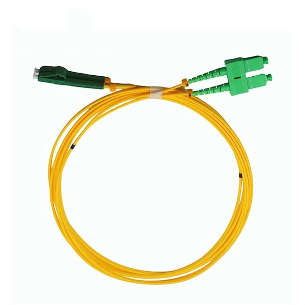
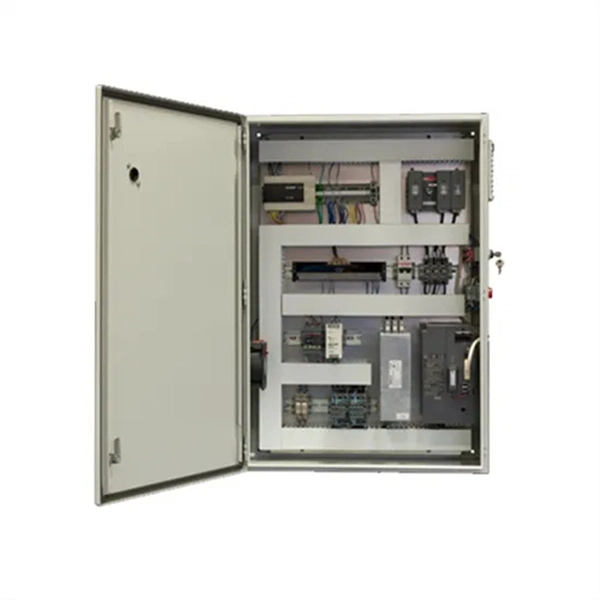
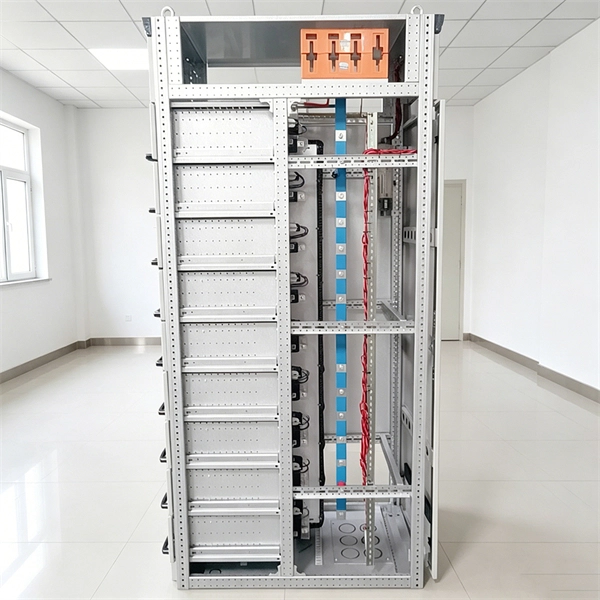
The XL type low-voltage power distribution cabinet uses domestically designed new components. The enclosure is made of bent steel plates, featuring a compact structure, easy maintenance, and flexible circuit scheme combinations. The 19-inch rack-mounted end box is a passive component for terminal distribution of trunk cables in fiber-optic communication systems, with tools for easy connection and distribution of fiber optic circuits. Sopto offers 19 Inch Rack Drawer Distribution box (Fiber Patch Panel) and 19 Inch Rack. 2 Core Fiber Optic Distribution Indoor Box (wall mount box type) © 2024 E-Talk Maldives. Nuomak is proud to announce a new cooperation with a client in the Maldives, for whom we have manufactured PS cabinets, MCCBs, and transparent waterproof electrical distribution boxes. These products are specially designed to meet the challenges of high humidity, salt spray, and harsh coastal. Need assistance? Let us help you with your questions and queries. Send a message to Viber: 7317894 Promotions, new products and sales. Directly to your inbox. Besides air circuit breakers and fuses for circuit protection, the. The electrical enclosure is made of wear-resistant and rust-resistant stainless steel, which can be widely used in indoor and outdoor applications, such as power, construction and other industries; allowing your equipment to be well protected in harsh environments. · Easy installation and easy.
[PDF]
Different methods have been developed to measure cable forces, including the traditional direct strain measurement method, the oil pressure meter method, the low-cost vibration frequency method, the high-accuracy magnetic flux sensor method in the lab., and acoustic. This study aimed to develop a spiral deployment scheme of distributed fiber optic sensors (DFOS) and to monitor/assess the post-tensioned force in seven-wire twisted steel cables, based on the pulse-pre-pump Brillouin optical time domain analysis. Each DFOS was placed in a spiral shape between two. Distributed Optical Fiber Sensing (DFOS) transforms standard fiber optic cables into powerful sensors capable of detecting temperature, strain, and acoustic signals at thousands of measurement points over long distances. Such capabilities. l method of measuring force by means of bending a Fiber Fabry-Perot-{FFP-) resonator is described. This interferometric FFP-sensor is easily applicable to AC orce measurements, but makes temperature compensati on schemes necessary if DC ntity that can various measuring parame, accelerat of di. Distributed sensors hold a unique position in the realm of sensing technologies. Unlike point sensors, they can measure and provide a continuous spatial distribution of a physical quantity, effectively creating a mapped profile of the parameter of interest. A well-known example is RADAR, and more.
[PDF]

Key finding: This paper develops analytical models and design procedures of ultra-wideband Wilkinson power dividers using linearly tapered transmission lines (TTLs) which provide size reduction and broadband performance. Read more. Power dividers are the passive electronic equipment used for splitting the power. They are now being employed in a variety of communications applications such as telephonic, antennas configurations, mobile connectivity, internet technology, & optics, etc. They come up with very low loss, operate at. RF and microwave power splitters and dividers create two copies of the same signal, while ideally preventing crosstalk between the outputs. Doing this with minimal loss while maintaining signal integrity is a challenge. In this article we explain how power splitters work and what the tradeoffs are. The rise of wireless connectivity requirements for applications such as Internet of Things (IoT), cellular, and automotive electronics is resulting in systems that are increasingly using RF signals, components, and subsystems. Often, designers need to direct these signals to more than a single. A power divider is a passive electronic device used in radio frequency (RF) and microwave applications to split an input signal into multiple output signals with equal or specified power levels, while maintaining impedance matching to minimize signal reflection and loss. How can power dividers.
[PDF]

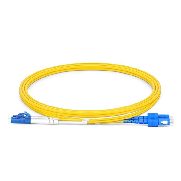
This article provides a detailed technical comparison between fiber optic and copper cables, offering a clear perspective for engineers, network architects, and procurement managers. The core distinction between the two technologies lies in the physics of data. There are significant differences in performance between ADSS cables (all-dielectric self-supporting optical cables) and traditional optical cables, which are mainly reflected in the following aspects: 1. This type of fiber optic cable is designed to support its own weight without the need for additional support structures like messenger wires. The ADSS. There are several factors to assess when deciding which cable type is right for your application, including speed of connection for new customers, ease of changes and repairs, installer certification requirements, and the ability to expand the network over time. ADSS Fiber Optic Cables are a type of optical fiber cable designed specifically for. All-dielectric self-supporting (ADSS) cable is a type of optical fiber cable that is strong enough to support itself between structures without using conductive metal elements. It is used by electrical utility companies as a communications medium, installed along existing overhead transmission.
[PDF]