To use a power meter for fiber optic testing, always clean connectors first with lint-free wipes or click-to-clean tools. Select the correct wavelength and set your reference. You measure optical power in dBm or insertion loss in dB. Consistent procedures ensure accuracy. Verify light travels from. The most basic fiber optic measurement is optical power from the end of a fiber. This measurement is the basis for loss measurements as well as the power from a source or presented at a receiver. Typically both transmitters and receivers have receptacles for fiber optic connectors, so measuring the. An optical power meter measures the strength of light traveling through a fiber optic cable, giving you a reading in dBm (decibels relative to one milliwatt). This article will guide you through the methods, instruments, and key considerations for measuring fiber. Fiber optic cabling is the high-performance core of today's datacom networks. As network speeds and bandwidth demands increase, fiber performance requirements have become more stringent. Fiber testing is more important than ever. An OPM uses a photodiode to generate an electrical current proportional to optical power.
[PDF]

Optical transmission windows are specific wavelength ranges where light travels through fiber with minimal attenuation (signal loss) and dispersion (distortion). These low-loss windows are essential for maintaining the performance and reach of fiber optic communication systems. Fiber optic cable is a type of cabling that contains one or more optical fibers for transmitting data at high speeds and/or over long distances using light. These fibers are most commonly made of glass and are very thin, typically less than a tenth of the width of a human hair. Fiber optic cable. This is your "QuickStart" guide to testing fiber optic cable plants, patchcords and communications equipment with a fiber optic light source and power meter. We'll give you the basic information you need and provide some printable references. Optical power, required for measuring source power, receiver power and, when used with a test source, loss or attenuation, is the most. Fiber optic loss testing is an essential part of maintaining reliable, high-performance fiber optic networks because it helps identify potential issues and ensures that the system meets the required performance specifications. In this blog, we'll explore what a power meter and light source are and. This part of IEC 61280 is applicable to the measurement of attenuation of installed optical fibre cabling plant using multimode optical fibre.
[PDF]
YOA Cable, Africa's largest optical fibre cable manufacturer, is known for delivering world-class optical fibre products and exceptional customer service. We anticipate market needs, innovate and constantly refine our manufacturing processes and products to deliver faster speeds and more flexible. Unleash the potential of our premium duct fiber cables, designed for seamless connectivity and long-lasting performance in all environments. Discover tailored solutions for your fiber infrastructure needs. From consulting to supplying top-quality accessories, we're your trusted partner in Africa. Welcome to CP Cables Ltd, your one-stop company for high-quality Fiber Optic products and accessories. Our extensive range of products includes Fiber Optic cables, connectors, adapters, splitters, transceivers, ONTs, patch panels, and more. Take your customers' internet connectivity to the next. Yangtze Optics Africa (YOA) Cable (Pty) Ltd, is an optical fibre cable manufacturer located in the Dube Tradeport Industrial Development Zone in Kwa-Zulu Natal, South Africa. Established in 2016, through the partnership of Yangtze Optical Fibre and Cable Joint Stock Limited Company (YOFC) and. The Chinese company is Africa's largest optical fibre cable manufacturer. The 14,000m² fibre optic cable factory at Dube TradePort.
[PDF]
It emphasizes the importance of considering mechanical and environmental aspects, referring to the IEC 60794-2 series for technical specifications. The document details the characteristics of optical fibers and cables, including transmission, microbending and macrobending. Nowadays, optical communications are the most requested and preferred telecommunication technology, due to its large bandwidth and low propagation attenuation, when compared with the electric transmission lines. Besides these advantages, the use of optical fibers often represents for the telecom. As environments are becoming increasingly harsh, the ability of optical fiber cable to withstand such environments is of the utmost importance to outside plant users. Laboratory accelerated aging environments have long been used as a measure to predict field performance of optical fiber and cables'. This study investigates the strain transfer mechanism for different types of fiber optic cables while embedded in concrete cubes, sustaining a boundary condition which features a displacement discontinuity. The strain transfer mechanisms for different cables are compared under increasing strain. This document outlines the recommendations for single-mode optical fiber cables used in telecommunication networks within buildings, focusing on their mechanical and environmental characteristics. It specifies that these cables must comply with standards such as ITU-T G.
[PDF]
3 specifies performance and transmission requirements for premises optical fiber cable, connectors, connecting hardware, and patch cords. Optical fiber transition methods used to connect cabling from an array connector to simplex or duplex connectors are also. ANSI/TIA-568-C. (FOA) was founded in 1995 to help develop the workforce to build the fiber optic networks to support a rapid expansion in communications and the Internet. The charter of the FOA was to promote professionalism in fiber optics through education, certification, and. ANSI/TIA‑568. 3‑E “Optical Fiber Cabling and Components Standard” was developed by the TIA TR‑42. 11 Optical Fiber Systems Subcommittee and published in September, 2022. A full catalog of TIA specs is at org/ Learning More About Standards and Codes There are a number of ways of finding out more about cabling. This specification covers the general requirements and characteristics for cables utilizing optical fibers for signal transmission. NOTE: The base document is not DLA Land and Maritime managed and is only here as a courtesy. Please use ASSIST Quick Search to ensure you have the latest version. This. This section covers Agency requirements for fiber optic service entrance cables intended for aerial installation either by attachment to a support strand or by an integrated self-supporting arrangement, for underground application by placement in a duct, or for buried installations by trenching.
[PDF]
Fiber optic cables often follow a color-coding system to indicate their type: Single-mode fibers - Typically yellow. Multi-mode fibers (OM1 & OM2) - Usually orange or sometimes gray. Choosing the right type of fiber optic cable is essential for reliable and cost-effective network performance. The two main types — Single Mode (SM) and Multimode (MM) — differ in construction, performance, and application. This guide explains how to identify them by appearance, labeling, and. When figuring out if a fiber cable is single mode, one must know the different classifications. Essentially, fiber optics are mainly categorized as: Single Mode Fiber (SMF): This type features a small core and uses laser technology to send a single light mode. Single mode fibers are used for. Knowing how to tell the difference between single mode and multimode fiber is crucial for network efficiency; the core distinction lies in the fiber's core diameter and how light travels through it, affecting bandwidth, distance, and cost. This allows for a single mode of light to travel through the core. With clear tables and updated details, it serves as a comprehensive reference for technicians handling modern fiber optic installations. We'll cover single mode, multimode, and armored fiber cables below. This small diameter core, typically around 9 microns in diameter, allows only one.
[PDF]

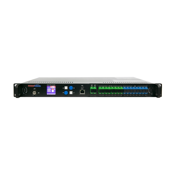
Regularly testing fiber optic cables helps minimize network downtime, lengthens the network's longevity, reduces maintenance requirements, and helps support network reconfiguration and upgrades. Fiber optic testing ensures the performance and reliability of fiber optic networks. Key tests include: Effective fiber testing utilizes advanced tools such as Optical. Fiber optic testing for continuity is crucial in ensuring that light transmits through fiber optic cables without interruptions, safeguarding seamless data transmission. This guide talks about the primary methods and tools for effective continuity testing in fiber optic cable networks. Insertion loss testing confirms whether the cable meets design loss budgets. OTDR testing identifies events along the fiber length, including: OTDR is essential for long-distance FTTH feeder and distribution cables. After the cables are installed and terminated, it's time for testing. For every fiber optic cable plant, you will need to test for continuity, end-to-end loss and then troubleshoot the problems. If it's a long outside plant cable with intermediate splices, you will probably want to verify the. We'll explain why it's vital to test fiber optic cables, the three most popular methods, and when you should use them. Why Testing Fiber Optic Cables Matters? Regular testing of fiber optic cables is not just a preventive measure; it's an.
[PDF]
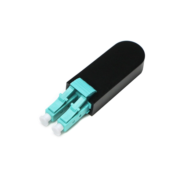
Find accurate cable prices in Uganda based on brand, quality, and manufacturer. Compare top suppliers, check MOQs, and get the best deals. Click to explore verified options today!. A 100-meter (328 ft) HDMI fiber optic cable is an active hybrid cable (fiber + copper) designed for. 1M LC_LC DUAL FIBER PATCH CORD: High-performance duplex multimode fiber optic cable with LC. Type: High-speed HDMI 2. Resolution Support: Capable of supporting 4K Ultra HD. Optical Audio Cable, 1. BOX 75720, PLOT NO 6 OPP. VICTORIA UNI (ESSO CORNER), JINJA ROAD, KAMPALA, UGANDA Copyright © Tronic Uganda Limited All Rights Reserved. The Ugandan cable market is rapidly evolving, driven by digitalization and infrastructure development. Prices are tightly linked to brand reputation and manufacturer sourcing, creating distinct tiers. Buyers must navigate between premium international brands, reliable mid-tier options, and. Cable Corporation Ltd was founded in 1968 and is today Uganda's oldest and largest cable and conductor manufacturing company. LV and Domestic Cables, and Transmission Conductors. Cable Corporation Ltd has two divisions. Cable Division and Engineering Division. Entire range of domestic cables – from. Volza's Global Partner Finder scans 3. 5 billion+ shipment records with 20+ precision filters to uncover the most reliable and economical suppliers for you. Volza's data confirms a robust and dependable Optical Fibre Cables supply network.
[PDF]

Find and discover Cable manufacturers and suppliers for all products in Malta, featuring details on their shipment activities, trade volumes, trading partners, and more. View all cable buyers based on products in Malta. Use the full potential of Europe's leading B2B marketplace. Subscribe to global trade data intelligence to discover new business. SM CABLES is a private company duly registered and approved by the local authorities for the Manufacture of Low Voltage Cables and forms part of a group engaged in building construction and electrical trading activities. As a manufacturing base that commenced in 1996, SM CABLES had acquired all the. We supply a range of both indoor and outdoor fibre optic cables that have different construction types, such as tight buffer, loose tube and microcable, to suit different application types be it for direct burial, duct installation, aerial (figure-8 and self-supporting) or blown fibre applications. Network Infrastructure Design, Installations, copper and fibre termination, cable laying, testing and certification. Overhead & Underground Cable Installations and Cable recovery. "At Conversa, our mission is to use our expertise and experience to create an effective and ethical match between the. Who we are, and what we stand for. As a manufacturing base that commenced in 1996, SM (Cables) acquired all the.
[PDF]

Optical cable lines lightning protection and strong current protection are achieved by avoiding, guiding or discharging them underground to prevent lightning and strong current from causing damage to the optical cable lines themselves, communication equipment and personnel. Since the lightning. ntly, there are a limited number of industry documents that address the requirements for optical fiber cables near high voltage circuits. One standard that has been developed by the Institute of Electrical and Electronics Enginee s, Inc (IEEE) is 1222, “IEEE Standard for All-Dielectric. The Fiber Optic Association, Inc. (FOA) was founded in 1995 to help develop the workforce to build the fiber optic networks to support a rapid expansion in communications and the Internet. ” It defines the requirements for ADSS cables placed aerially in a high. This Recommendation provides a procedure to protect the telecommunication lines using fibre optics against direct lightning discharges to the line itself or to the structures that the line enters. The protection procedure is related to the exposure of the line to direct lightning discharges and. Armored Cable: For direct burial or areas prone to crushing, use armored fiber optic cables that have an additional layer of metallic or non-metallic protective sheathing. Cable Trays and Ladders: In data centers and industrial settings, use cable trays or ladders to support runs, keeping them off.
[PDF]
Indoor cable (PVC or LSZH jacket) is cheaper but unsuitable for wet or UV-exposed environments. Fiber optic cables are essential components in today's broadband, FTTx, and data center networks. Whether you're planning a national fiber rollout or sourcing cables for enterprise infrastructure, understanding how fiber optic cable pricing works can help you budget more effectively and make better. Buyers typically pay for fiber optic cable by length, fiber type, and installation complexity. Main cost drivers include cable grade (indoor vs outdoor, armoured), distance, and labor for trenching, splicing, and termination. This guide presents ranges in USD and practical price estimates to help. Optic cable price represents a crucial consideration in modern telecommunications infrastructure, reflecting the complex interplay of manufacturing costs, technological advancement, and market demand. These essential components of digital communication networks vary in price based on several key. * Disclaimer: Prices fluctuate based on raw material indices (Glass/Copper/Polymer) and cable core count (e. This feature makes them ideal for high-voltage power lines where both grounding and data transmission are needed. On the other hand, standard fiber optic cables 4 focus solely on data transmission and are.
[PDF]

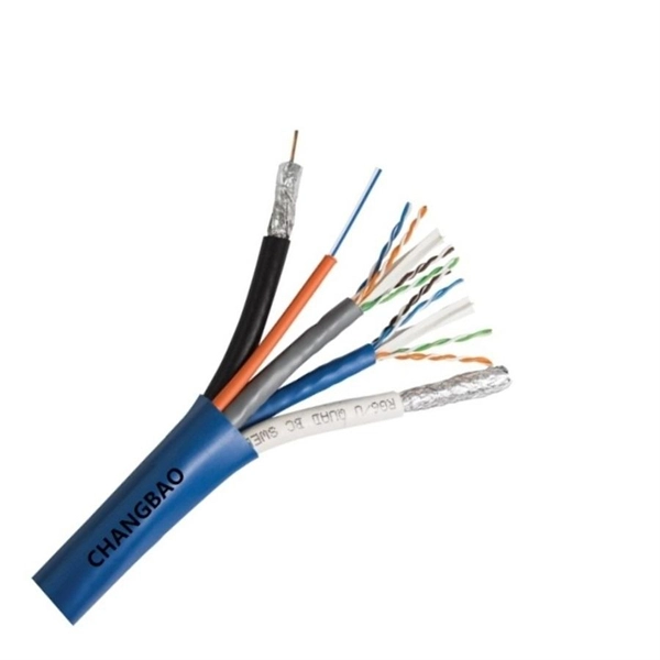
The basic structure of optical fiber consists of three primary components: the core, the cladding, and the buffer coating. The core is the central part of the optical fiber through which light is transmitted. An optical fiber cable is a complex structure designed to protect fragile glass fibers that transmit digital data using light signals. This advanced cabling solution allows fast, secure data transfer and telecom over long distances. Understanding the components within a fiber optic cable enables. In this blog, we will delve into the fundamental components and structure of optical fiber to gain a better understanding of this revolutionary technology. At its core, optical fiber is a thin, flexible, and transparent fiber made of glass or plastic, which serves as a medium for transmitting light. They consist of three main components and are available in several structures suited to different uses. In this article, discover in detail these components and the various structures of fiber optic cables. The core: made of silica, molten quartz, or plastic, in which optical waves propagate. Dielectric material conducts.
[PDF]
This article outlines five specific steps for repair: 1) Identify the break; 2) Cut out the damaged section; 3) Strip the cable; 4) Trim the fiber ends; 5) Test the repair. DIY fiber optic cable repair kits are increasingly popular for those who prefer home repairs. Before diving into repairs, it's essential to grasp the basics of fiber optic cables. These cables consist of a core (glass or plastic) that carries light signals, surrounded by cladding to reflect light inward, a buffer for protection, and an outer jacket for durability. Single-mode fibers (SMF). With the right tools and techniques, you can efficiently repair damaged fiber cables and restore reliable performance. The first step requires that you find the damage. To do this, you can use an OTDR, Optical Time Domain, Reflectometer. This is a testing device that looks at optical signals in the cable which can identify irregularities in the structure. This involves a set of specialized equipment such as a fusion splicer, fiber cleaver, and fiber stripper, among others. When it comes to ensuring nice network experiences for users, the condition of a fiber. A cut or damaged fiber optic cable can disrupt your network, but it is repairable with the right tools and techniques.
[PDF]
This list includes both standards-based and real-world technical cable types utilized in fiber-optic infrastructure, telecoms, enterprise, and outdoor applications. • OFC: Optical fiber, conductive• OFN: Optical fiber, non-conductive• OFCG: Optical fiber, conductive, general use.
[PDF]

South Korea Exports of optical fibres, optical fibre bundles and cables to Slovenia - data, historical chart and statistics - was last updated on July of 2024. 37 Million during 2022, according to the United Nations COMTRADE database on international trade. According to Volza's Fiber Optic Cables Import data of Slovenia, there are a total of 50 Fiber Optic Cables Importers in Slovenia, importing. In 2024, the Slovene market for optical fibers, bundles and cables was finally on the rise to reach $X for the first time since 2020, thus ending a three-year declining trend. Over the period under review, consumption, however, showed a pronounced descent. is a system integrator that offers services for optical and coaxial networks, highlighting its expertise in telecommunications infrastructure. Their comprehensive solutions are designed to support the operational success of businesses across various sectors. FMC Telco Group specializes. Fibernet is specialized in BtoB segment, serving businesses across all sectors operating in five main business segments: Highly skilled and motivated team is at your service, across the country or abroad to meet your requirements!. We offer a wide sales program cables and connectors and installation accessories. There is a virtual catalog of our latest offers. Our mission is to offer first-class quality for our clients, competitive prices and excellent service.
[PDF]