Product Range: PLC splitters, FBT splitters, fiber optic adapters, patch cords Price Range: $5 to $150 depending on splitter ratio and specs Overview: TTI Fiber is a global supplier known for quality optical components. FBT (Fused Biconical Taper) Fiber Optic Splitters. These devices splits the fiber optic signal from a single Input to two Outputs. Available in 50/50, 30/70, and 90/10 spit ratios. A fiber optic splitter is different from WDM. WDM can divide the. FBT (Fused Biconic Taper) Coupler Splitter is a commonly used fiber optic coupler and splitter for distributing optical signals to multiple output channels. FBT splitters are reliable and cost-effective, typically used for smaller split ratios like 1x2 or 1x4. The physical packaging or form factor of a splitter is crucial. FBT Coupler Splitters is widely accepted and used in passive optical networks, especially for instances where the split configuration is smaller (1×2, 1×4, etc. FBT is the traditional technology in which two fibers are placed closely together, typically twisted around each other and fused. FBT Fiber Splitter, also known as a fiber optical coupler, separates fiber optic light into many portions using a predetermined ratio. Unlike PLC splitters, FBT splitters employ distinct splitting methods and may be constructed using singlemode, multimode 62. 5, or multimode 50 fibers.
[PDF]

The box is typically composed of several parts, including the enclosure, the splitter module, and the connectors. An optical cable split fiber box is a device used in fiber optic communication networks to split the signal from one input into multiple outputs, allowing multiple devices to be connected to a single fiber optic cable. This provides users with a dependable and high-speed network service and little to no wait times. There is no need for an FDB if there is no. In modern FTTH (Fiber to the Home) and optical communication networks, three types of fiber distribution products are widely used: Splitter Distribution Box, ODF (Optical Distribution Frame), and Fiber Terminal Box. Although they all belong to the optical distribution and management system, their. A fiber optic splitter is a passive optical component that divides a single incoming optical signal into two or more outgoing signals, or combines multiple incoming signals into one. It can divide the input optical signal into multiple output optical signals to meet the fiber optic access needs of multiple terminal devices. This type of device plays an important role in passive. In this kind of fiber cabinet, the backbone fiber optic cable usually does not connect to optical splitters. However, in some metropolitan area, the backbone fiber cable will.
[PDF]
A PLC Splitter takes one optical signal and splits it into many outputs. This helps share signals in fiber optic networks. Pick the split ratio that matches what you need. Lower ratios work for fewer users. Choose the connector type like SC . PLC optical splitters (planar waveguide optical splitter) is a key component in optical fiber communication networks and is widely used in optical fiber distribution systems such as FTTH (fiber to the home) and PON (passive optical network). A fiber optic PLC splitter distributes a single optical signal into multiple outputs with high uniformity and low loss, making it ideal for. PLC splitter, also called Planar Waveguide Circuit splitter, is a device used to divide one or two light beams into multiple light beams uniformly or combine multiple light beams to one or two light beams. It is a passive optical device with many input and output terminals, especially applicable to. What Is a PLC Fiber Splitter? A PLC (Planar Lightwave Circuit) splitter is a passive optical device that evenly distributes optical signals into multiple output ports using silica waveguide technology. Choose the connector type like SC, LC, or FC. This. That's where PLC splitters come in. These compact passive components help service providers and network engineers distribute a single optical signal across multiple outputs without the need for power or complex configurations. If you're building or upgrading a fiber network and wondering what a PLC.
[PDF]

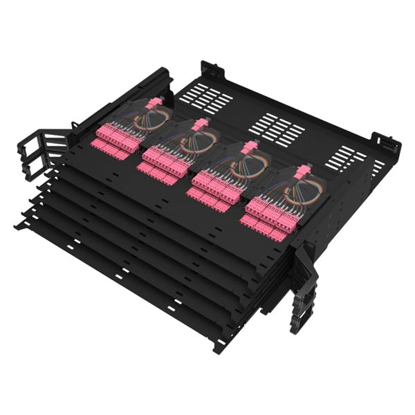
This unit is a nine output Composite Splitter with built in distribution amplifier. It is used to distribute composite video signals to multiple destinations with compatible outputs. Composite Splitter provides multiple outputs that are identical to the Video input signal. Check each product page for other buying options. Shop products from small business brands sold in Amazon's store. Learn more Need help? Discover optical fiber splitters designed for home. Optical splitters and couplers split or combine light—distributing signals injected into a single fiber strand to multiple fibers, enabling point to multi-point communication in Fiber To The Home (FTTH) networks based on ITU. T PON standards such as GPON, XGS-PON and new 25 and 50G standards. Cables Plus USA can supply custom fiber optic splitters to meet your specific requirements. Available in PLC splitters, also called Planar Lightwave Circuit. As well as FBT splitters Fused Biconical Taper splitters, which are two or. Only 1 left! Get the best deals on Corning Cable Splitters and Adapters and find everything you'll need to improve your home office setup at eBay. Fast & Free shipping on many items!. FS PLC Fiber Optic Splitters, Bare/Blockless/ABS/LGX Splitter/Rack Mount Types, support 1xN light distribution, with low IL and PDL for high-reliability transmission. Deploying compact FS PLC Splitters to simplify your networks, perfectly fits your PON, EPON, FTTX, etc. ZIP code to view pricing.
[PDF]

Fiber optic pigtails are short, single, or multi-strand pieces of optical fiber cables with a connector on one end and exposed fiber on the other end. They are typically used to terminate fiber optic cables and connect them to patch panels, equipment, or other termination points. Fiber pigtails are simple in appearance, yet essential in function. Despite this ubiquity, they remain a source of confusion for procurement teams and junior installers alike—especially when it comes to connector type selection, polish type, and the tradeoffs between mechanical. Fiber Optic Pigtails, also known as pigtailed fibers, consist of an optical fiber connector and a section of optical cable. Characterized by having an optical fiber connector on one end and a bare fiber end on the other, they are primarily used to connect optical transceivers or other optical. A Fiber Optic Pigtail Complete Guide: As per types, connectors, and applications. In such contemporary fiber optic communication systems, low-loss, and connectivities, which have reliability, are crucial for not only maintaining high-speed but also high-quality data transmission. It is usually suitable for field termination using a mechanical or fusion splicer. Compared with quick termination or epoxy and polish connections placed on the field.
[PDF]
The securing, storing and supporting of fiber optics and splices makes up an important step of fiber optic deployments in the field. Whether connecting to aerial or underground cables, telecommunication.
[PDF]

The BA-1 device produces step attenuation of a laser beam to a maximum of about 44 dB . With the preattenuator beam splitter, denoted by SI, this range can be extended as much as another 3 0 dB. The various low level beams generated by BA-1 can be used for detector respon-sivity and. Danielson, B. (1977), Measurement procedures for the optical beam splitter attenuation device BA-1:,, National Institute of Standards and Technology, Gaithersburg, MD, , https://doi. 77-858 (Accessed February 10, 2025) If you have any questions about this publication or. Beam splitters are optical devices that play a crucial role in various scientific and industrial applications. They are used to divide a beam of light into two or more separate beams. NBS interagency report is a publication of the U. The papers are in the public domain and are not subject to copyright in the United States. The BA-1 system is designed for use at. The attenuation ratios of these wavelengths are calculated values. An analysis of the estimated uncertainties is. SPLITTER ATTENUATION DEVICE BA-1 B. Danielson Measurer::ent procedures are described for the step attenuation of laser bearriS up to 44 dB using a specially constructed attenua- tor box (BA-1). a laser beam) into two (or sometimes more) beams, which may or may not have the same optical power (radiant flux).
[PDF]
Cable is usually faster than DSL as it has more bandwidth. Fiber internet, on the other hand, offers faster speeds and higher capacity overall. This is made possible because light signals travel faster and carry more information than electrical signals. Cable internet connections sit somewhere in the middle in the internet hierarchy: faster than DSL and satellite, but behind fiber. These connections utilize coaxial cables, which are made of copper, instead of fiber optic cables, which use small, flexible strands of glass or plastic. Because it's a. Whether powering a 5G network across a city or delivering gigabit internet to a rural household, fiber optic cable speed defines the backbone of digital infrastructure. This comprehensive guide explores what drives fiber optic speeds, how they compare to traditional alternatives, and how Dekam. Cable transmits data through copper coaxial cables (with an inner conductor and a protective outer jacket). Fiber-optic internet, also known as "fiber", transfers light signals along thin strands of glass.
[PDF]

To use a power meter for fiber optic testing, always clean connectors first with lint-free wipes or click-to-clean tools. Select the correct wavelength and set your reference. You measure optical power in dBm or insertion loss in dB. Consistent procedures ensure accuracy. Verify light travels from. The most basic fiber optic measurement is optical power from the end of a fiber. This measurement is the basis for loss measurements as well as the power from a source or presented at a receiver. Typically both transmitters and receivers have receptacles for fiber optic connectors, so measuring the. An optical power meter measures the strength of light traveling through a fiber optic cable, giving you a reading in dBm (decibels relative to one milliwatt). This article will guide you through the methods, instruments, and key considerations for measuring fiber. Fiber optic cabling is the high-performance core of today's datacom networks. As network speeds and bandwidth demands increase, fiber performance requirements have become more stringent. Fiber testing is more important than ever. An OPM uses a photodiode to generate an electrical current proportional to optical power.
[PDF]

Fiber Optic Welding How To Joint Fiber Optic Cablesplicing fiber optic cable,fiber optic splice,fiber optic,fiber optics,fiber splice,how to splice,fibre opt. The optical fiber connection adopts the fusion splicing method. The whole process is similar to the welding of metal wires, and it is generally carried out by electric isolation. At the moment, there are two methods of connection: Thermal welding of optical fibers consists in bringing the ends of the conductor to melting using a fiber optic splicer, and more specifically - located inside the electrodes. The welded ends are then pressed and a weld is formed. The most work is waiting for installers, whose tasks can be divided into several stages: In this part, we will deal with the second stage, i. welding, which is considered to be one of the most difficult parts of installers' work in. Open the stripping tube and wipe the grease on the optical fiber with toilet paper and alcohol cotton. On the welding disc, make the optical fiber precoil first and cut the optical fiber into an appropriate length to facilitate the coil fiber work after welding. Add heat shrink tube. Procedure. Another method is to use the so-called mechanical welding. It uses special parts that are prepared in advance to connect the two ends. Thanks to this, you can connect two ends of the cable with a ready-made splice, without the need to use an optical fiber splicer. While this method may appear to be.
[PDF]

A fiber-optic splitter, also known as a beam splitter, is based on a quartz substrate of an integrated waveguide optical power distribution device, similar to a coaxial cable transmission system. The optical network system uses an optical signal coupled to the branch distribution. The fiber optic. In the backbone of modern Fiber-to-the-Home (FTTH) networks, optical splitters serve as the unsung heroes that enable cost-efficient connectivity for millions of subscribers. By dividing a single optical signal from a central Optical Line Terminal (OLT) into multiple outputs for Optical Network. Optical splitter, also called optical beam splitter, is an integrated waveguide optical power distribution device that can split an input optical signal into two or more output optical signals, and the optical input power is evenly distributed on all output ports. For example, an optical splitter. The answer lies in a small device. We call it an Optical Splitter. This device is the heart of Passive Optical Networks (PON). It allows service providers to save money. It helps them distribute bandwidth efficiently. In this article, we explain the definition, working principles, types, and. An optical splitter is a device that divides light transmission in a network into multiple output ends. It plays a crucial role in facilitating network interconnections.
[PDF]

However, essentially, optical fiber patch cords are more like "finished connection lines", while optical fiber pigtails are "semi-finished connectors". The difference in this core positioning determines the vast disparity between them in structure, connection methods. Executive Summary: A fiber optic pigtail is one of the most commonly specified yet least understood components in structured cabling. Get the wrong connector type, the wrong polish, or skip proper fusion splicing technique—and you're looking at elevated signal loss, increased back reflection, and a. When you build or upgrade a fiber network, the same four words pop up everywhere— fiber optic (bare fiber), pigtail, patch cord, optical cable. They're related, but they are not interchangeable. Mixing them up drives costs higher, increases loss, and slows your rollout. The good news? Once you nail. A fiber pigtail is typically a fiber optic cable with one end factory pre-terminated fiber connector and the other exposed fiber. It is usually suitable for field termination using a mechanical or fusion splicer. The connector end plugs into devices like transceivers or patch panels, while the bare end is typically fusion spliced to a fiber optic cable. This setup ensures. As outlined in T13: Fiber Optic Fundamentals, an optical fiber is a coaxial cylindrical dielectric waveguide with a core refractive index exceeding that of its cladding.
[PDF]

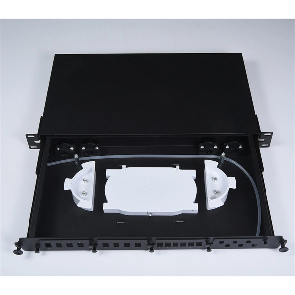
If you are ever in need of checking your ONT, this video will show you how to do so and what it is you are looking for. Always remember to securely close the box afterwards to prevent any damage to the facilities inside. more. A fiber termination box is the standard instrument used in fiber optic networks to connect, secure, and protect optical fibers at the terminating point. It functions as a junction between the incoming fiber cable and the outgoing customer-side fiber cable, where one fiber can be spliced, patched. Open the Fiber optic terminal box. Check and prepare installation tools and accessories. Prepare the cable according to the design. An ONT, or Optical Network Terminal, is the box where your fiber internet connection enters your home to power your fiber network. Your ONT is typically located in your garage, basement or outside your home within a few feet of your home's power box. It serves as a termination point for optical fibers, providing a secure and organized space for connecting and managing fiber optic cables. A fiber pigtail is a specific hardware connection used for cable termination. Proper installation and maintenance of FTBs are essential to ensure the reliability and performance of the network infrastructure.
[PDF]
Fiber testing is the process of verifying the performance of optical fiber cabling. This process includes a range of tests and measurements such as insertion loss, optical return loss, and fiber length. It encompass.
[PDF]
The beam splitter is one of the important elements in optical waveguide circuits. To improve the performance of an optofluidic beam splitter, a microchannel including a two-stage main channel with divergent side walls and two pairs of inlet channels is proposed. Besides, the height of the inlets. M. Oulad Haddar; Improvement of optical characteristics of silicon based 1×3 beam splitter with photonic crystal waveguide. 20 January 2022; 2440 (1): 020001. 0075004 In this work, we propose a new structure of 1×3. In the second step of this work we propose an optimization of the conventional splitter design leading to suppression of the asymmetric splitting ratio to one-third of its initial value and to the improvement of the losses by nearly 2 dB. In addition, 50% size reduction of the designed structure. d for the power splitting ratios are vital for the adaptive optical networks and photonic computing. Conventional mechanisms such as thermo-optic, free-carrier, or mechanical tuning are usually volatile and require continuous p wer, limiting their suitability for low-frequency and low. Optical and Quantum Electronics This paper aims to study the design, simulation, and optimization of low-loss Y-branch passive optical splitters up to 64 output ports for telecommunication applications. For a waveguide channel profile, the standard material silica-on-silicon is used.
[PDF]