
This guide details the necessary physical and digital steps to connect your fiber line and activate your internet service. The fiber optic cable does not plug directly into a standard home router because the signal type must be translated. Fiber optic networks are celebrated for their speed and reliability, but even the best systems can encounter problems. When issues like signal loss, slow speeds, or intermittent connectivity arise, systematic troubleshooting is key. This guide will walk you through diagnosing and resolving common. Fiber optic troubleshooting is the systematic process of identifying, diagnosing, and resolving problems within fiber optic communication networks. These networks are the backbone of modern data transmission, offering incredible speeds and bandwidth. However, even the most robust systems can. When your fiber optic network stops working, begin with a structured approach. First, check the basics—look for power issues on your optical network terminal and inspect all cables for visible damage. Many fiber internet problems come from dirty connectors or loose plugs, not major faults. The fiber line terminates at the Optical Network Terminal.
[PDF]

Explore our comprehensive SFP optical module selection guide for 2025. Learn about crucial factors like data rate, distance, fiber type, and compatibility to optimize your network performance and cost-effectiveness. Make informed decisions for your networking needs today!. SFP (Small Form-factor Pluggable) is a compact, hot-pluggable network interface module used to connect network devices (switches, routers, firewalls) to fiber optic or copper cables. They're essential for extending network distances and increasing bandwidth capabilities. Selecting the correct SFP module is not simply a matter of matching connectors. In modern Ethernet networks, choosing the wrong transceiver can result in link failures, speed mismatches, compatibility errors, or unexpected distance limitations. For network engineers, system integrators, and IT. At the core of these advanced networks are bidirectional SFP modules, also known as BiDi SFP transceivers—compact, cost-efficient devices that support high-speed data transmission and reception over a single optical fiber. By using different interfaces and single-mode or multimode fiber depending on the.
[PDF]
will introduce major upgrades to its Multi-Rail technology platform at ECOC 2025, targeting hyperscale optical transport with new efficiency, scale, and performance enhancements. Coherent Corp. SAXONBURG, PA, September 26, 2025 (GLOBE NEWSWIRE) – Coherent Corp. At the heart of the. SAXONBURG, Pa. At the heart of the. Simultaneously, coherent technology has emerged as the prevailing solution for Data Center Interconnection (DCI) applications, covering distances of 80~120km in the field of data communication. These evolving applications introduce new demands for coherent optical transceiver systems, steering the. Coherent optical module refers to a typically hot-pluggable coherent optical transceiver that uses coherent modulation (BPSK / QPSK / QAM) rather than amplitude modulation (RZ/ NRZ / PAM4) and is typically used in high-bandwidth data communications applications. Optical modules typically have an.
[PDF]
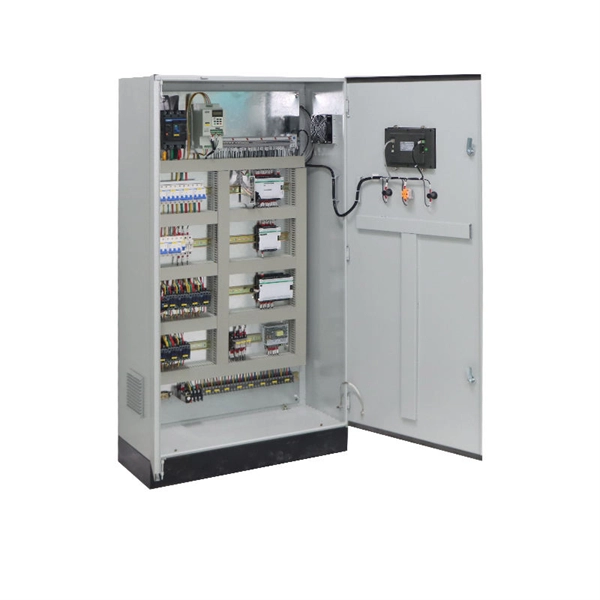
The strength and corrosion resistance of steel plate make it a common material for the box of the distribution box, and its good conductivity also ensures electrical safety. You can find distribution boxes made from various distribution box materials such as steel, aluminum, PVC, polycarbonate, high-density polyethylene, and thermoset plastics like SMC. Each distribution box material has its own special strengths. For example, you may need flame retardant features. The. The internal structure of the distribution box is designed to safely distribute power from the main power source to multiple branch circuits. It provides convenience for protection, control and maintenance. It helps control and distribute electricity to different areas. Inside, you'll find parts like circuit breakers and fuses that protect the system from problems like overloads and short circuits. These Distribution Cabinets are to be outdoor type nd to be fabricated out of 2 mm GI sheet steel. The body of the boxes shall have sufficient re- enforcement with suitable size of channels keeping a provision for fixin andle conforming to general.
[PDF]
Communication towers are tall steel structures used to raise antennas to higher elevations in order to extend service coverage and improve wireless communication performance. Antennas are typically mounted at the highest practical point to increase service radius. Pile Foundation: In areas with loose or unstable soil, deep foundations known as piles are driven into the ground. These piles are often made of concrete or steel and are designed to reach a stable layer of soil or bedrock, ensuring the tower remains secure. Raft Foundation: For heavy towers or. Modern communication tower technology & infrastructure represents the essential physical backbone of our global wireless world. This specialized field combines civil, structural, and electrical engineering to create the tall structures that support antennas for mobile networks. The construction of these towers requires careful planning, precise engineering, and skilled labor. In this section, we will delve into the. There are four main types of telecommunication towers: lattice towers, monopole towers, guyed towers, and stealth towers. These towers play a crucial role in enabling wireless communication by providing a platform for the installation of radio equipment and antennas. A typical communication tower.
[PDF]

This guide explains how to make 90° bends, vertical bends, tees, and offsets in wire mesh cable trays safely and professionally. Horizontal 90° Bend (Flat Bend) 2. Tee (T-Junction) Bend 4. Since the jaws of the bolt cutter drags a layer of zinc across the cut end and forms a protective layer. When a wire cable tray is cut, the fact that a. Wire mesh cable trays are widely used because of their flexibility and easy on-site modification. Unlike perforated trays, bends can be created directly at site without expensive fittings. Great if you are new or just forgot how to do it, this easy to follow guide makes it so simple. more The Easy Guide to. This involves a few essential steps to ensure a successful bending process. The first step in preparing the. The method for producing bridge bend elbows is as follows: Take a 90-degree cable tray bend elbow as an example, and apply the same principles for 45-degree bends accordingly. The length of the bottom side (bottom diagonal) after bending the cable tray should be equal to the width of the cable. OTHER THAN 90 ̊ JUNCTIONS Use this guide to learn the most effective installation practices when installing Cablofil tray. Each example of bends and tee's clearly illustrate proper tray cutting combined with recommended usage of Cablofil accessories. Engineers and contractors in North America and.
[PDF]
In an Ethernet patch panel diagram, each port on the patch panel is represented by a numbered or labeled square or circle. The diagram typically includes details such as the port numbers, cable types, and the devices connected to each port. Ethernet patch panel diagram is a visual representation of the connections between Ethernet cables and network devices, such as switches and routers. It provides a clear overview of how the network is structured, allowing network administrators to easily troubleshoot and manage the network. This information can be used to track the location of devices, their serial numbers, and their IP addresses. Change Management: Patch panel connection diagrams can be used to track. A patch panel is an essential component in a network system that provides a central location for connecting multiple devices or cables. The patch panel serves as. A pair of managed Gigabit Ethernet rack-mount switches, connected to the Ethernet ports on a few Panduit patch panels using Category 6 patch cables. (All equipment is installed in a standard 19-inch rack. Each port has a patch connection that links it to another port in another part of your building.
[PDF]
Home distribution boxes typically handle single-phase power supplies and contain 6 to 24 circuits. They include standard circuit breakers for lighting, outlets, and major appliances like water heaters and air conditioning units. This panel acts as the heart of an electrical network. It ensures that circuits are safe, organized, and easy to manage. A properly installed electrical distribution box is important for safety. Also called a distribution board, panel board, breaker panel, or electric panel, it is the central hub in an electrical system that divides incoming power into various subsidiary circuits. It helps control and distribute electricity to different areas. The boxes also store protective equipment devices. A distribution box, also known as a distribution board, electrical panel, or breaker box, is an enclosure that houses electrical components responsible for distributing electricity throughout a building. It receives power from the main electrical supply and divides it into separate circuits, each. A distribution box uses MCBs, RCDs, and busbars to protect circuits, prevent shocks, and ensure safe power distribution in homes and buildings.
[PDF]
Main distribution boards (MDB) manage and distribute electrical power from one or more sources to branch circuits in an LV distribution system. It provides circuit breakers for each branch circuit to prevent faults and incidents. Panelboards are designed to meet UL 67 and NEMA Standard PB1. What is the difference between a switchboard and a panelboard? Switchboards and panelboards provide a similar functionality in a power distribution system. Panelboards are typically flush mounted or surface mounted and are limited to a. A distribution board (also known as panelboard, circuit breaker panel, breaker panel, circuit breaker, electric panel, fuse box or DB box) is a component of an electricity supply system that divides an electrical power feed into subsidiary circuits while providing a protective fuse or circuit. According to NEC Article 100, branch circuits are the conductors between the final overcurrent device protecting the circuit and the outlet. This article deals with lighting and appliance branch circuits. The article also covers motors or. A panelboard is a distribution assembly designed to divide an incoming electrical feed into numerous smaller branch circuits. Each circuit is protected by its own circuit breaker. Inside a distribution box are components. multiwire). Branch device and terminates at another circuits are usually low current (30 amps or distribution center, panelboard, or load less), but can also supply high curre ts.
[PDF]
One key aspect of this progression is the advent and evolution of transceivers, specifically SFP, SFP+, SFP28, QSFP+, and QSFP28. Let's delve into each of these technologies to understand their specifications, differences, and applications. A Cisco compatible SFP list 2026 represents a validated inventory of optical transceivers that utilize Multi-Source Agreement (MSA) standards to provide identical functionality to Cisco Original Brand (OB) optics. Deploying these modules allows network architects to reclaim up to 80% of their. —— Explosive Growth of 800G/1. 6T Technologies, Scene-Based Selection + Finisar Original Solutions in One Stop In 2026, driven by AI computing power, optical modules have entered a critical era of rate iteration, technological restructuring, and scenario segmentation. 800G has become the mainstream. Choosing the right Small Form-factor Pluggable (SFP) transceiver is critical for network engineers and procurement specialists aiming to optimize performance, cost, and reliability. This SFP buying guide offers a detailed technical comparison, real-world deployment insights, and practical selection. ity with compelling economics. Our ONE Network platform simplifies management of Cambium Networks' wired and wireless broadband and network edge technologies. Our customers can f iness rather than the network. We mak. SFP+ 10G ZR is designed for stable 80km single-mode transmission where standard 10G optics fail.
[PDF]

The video tutorial demonstrates the depin and repin method for repairing automotive wiring harness connectors, specifically pigtails. It outlines seven easy steps to replace a pigtail connector, making it accessible for DIY enthusiasts and individuals dealing with electrical issues. This comprehensive guide will equip you with the knowledge and skills to accurately assess the integrity of a pigtail, helping you identify issues before they escalate into larger problems. We'll explore different testing methods, delve into the interpretation of multimeter readings, and offer. The latest in the line of Ford Flex Probe Kits, this newest release includes all the probes from the previous “D” kit, but now adds two each of the Micro Pin (. Additionally, all probes will now be printed with the tip size, helping technicians ensure usage of the properly sized tip. Short answer: An automotive wiring pigtail is a short section of wire with a pre-attached connector that lets you repair or replace a damaged plug without replacing the entire harness. It provides a plug-and-play repair solution that restores OEM fit, seal, and electrical reliability. Key steps. At FindPigtails. com, we specialize in high-quality, OEM connector replacement. Why pay thousands for a complete wire harness, when you can simply replace the damaged connector? We invite you to take a look at some of our instructional videos, for step-by-step guides of de-pin and re-pin procedures.
[PDF]
