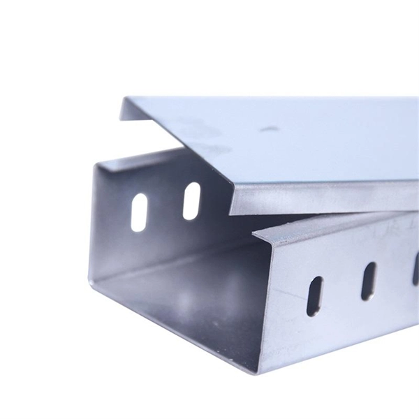
Cable Trays* — Max two 24 in. (610 mm) wide by max 6 in. (151 mm) deep open-ladder cable tray with channel-shaped side rails formed of 0. 54 mm) thick aluminum or min 0. In practice, cable tray dimensions are a system of interrelated measurements —width, depth, length, and material thickness—that directly affect cable fill compliance, heat dissipation, structural loading, and long-term expandability. From an engineering standpoint, cable tray dimensions are not. Perforated Cable Tray System expertly constructed from high-grade stainless steel, offering exceptional durability and resistance to corrosion. With side height 100mm. A properly designed and installed cable tray system will provide. Studs — Wall framing to consist of wood studs or channel shaped steel studs. Wood studs to consist of nom 2 by 4 in. Additional studs shall be used to completely frame. Best Size: Here, deep trays (75mm to 150mm) are used since power cables are typically thick and heavy. Data cables, such as your Wi-Fi or computer ones, are extremely sensitive. They do not get hot; however, they do not like to hang or sag. In case a data cable folds in an excessive manner, the. ect the minimum bend ra-dius for cables as they exit the bottom of the cable tray. A rung spacing of 6 to 9 inches (150 to 230 mm) is preferable when the cable tray cont d for instrumentation and control applications that require additional protec eferred to support and protect numerous small.
[PDF]

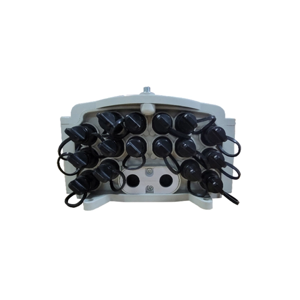
At its core, a fiber termination box combines hardware and software components to facilitate fiber optic connections. The hardware includes protective enclosures, splice trays, adapters, connectors, and patch panels. A Fiber Terminal Box (FTB) is a customer-side termination and distribution device used at the end of the optical network. It is small, so it is considered a mini version of the optical distribution frame or optical distribution frame (ODF). The number of ports of fiber optic junction boxes ranges from 8. A fiber optic junction box, also known as a fiber optic distribution box or termination box, is a protective enclosure that facilitates the connection and management of fiber optic cables. It serves as a central point for organizing and distributing optical fibers, ensuring efficient connectivity. Fiber termination boxes are essential components in modern telecommunications infrastructure. They serve as the critical junction points where fiber optic cables connect, splice, and distribute data signals efficiently and securely. Here's a structured breakdown. This article provides an in-depth comparison of fiber terminal boxes and junction boxes to help clarify their differences and deepen your understanding.
[PDF]

A typical fiber optic splice enclosure consists of several key components that work together to protect and organize the fiber splices. Standard enclosures contain: 1) Housing, 2) Cable fixation clamps, 3) Splice trays, 4) Sealing system. A splice box (also known as splice distributor) is a housing in which fiber optic cables begin or end. Fiber optics are fanned out in splice boxes that are situated at the end of fiber optic transmission paths. Optical cable joint box The optical cable joint box permanently connects two optical cables together and has a joint part for protecting components. The optical cable connection part, that is, the optical cable joint, is the part where the. An optical cable split fiber box, also known as a fiber distribution box or fiber optic splice closure, is a device used to terminate, splice, and distribute optical fibers. In this response, we will focus on the. This guide optimizes the original text by delving deeper into the three pillars of fiber network longevity: the impact of splicing technology, the strategic selection of splice boxes, and the essential maintenance protocols needed to ensure sustained, high-speed functionality. Fibre optic cables are manufactured in standardized lengths –.
[PDF]

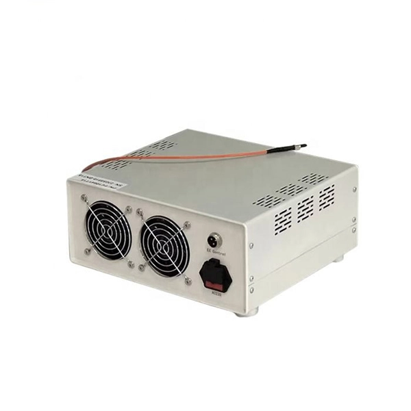
It connects to two independent power sources, enabling automatic switching to a secondary source during primary source failures. This seamless transition prevents disruptions to connected devices and enhances operational reliability. A dual power switching box is precisely the kind of gadget that guarantees a constant flow of electricity as it enables the user to shift the operational state between two different energy supplies. It can be found in homes, workplaces, factories, and anywhere else where sudden cuts of energy can. The ATS Dual Power Distribution Box plays a pivotal role in providing efficient low-voltage power solutions, ensuring that power flows seamlessly, even in the event of an outage. This comprehensive guide offers insights into the mechanisms and benefits of the ATS Dual Power Distribution Box. Transfer switches and sub panel boxes are key components in dual power switching cabinets. Transfer switches automatically switch between power sources during outages, ensuring uninterrupted power and system reliability. This redundancy ensures that if one power source fails, the other can immediately take over, minimizing downtime and preventing. A dual power switch helps you manage two power sources for one system. You can use it to keep your equipment working if the main power stops. This device quickly changes from the main supply to a backup source. This seamless transition.
[PDF]

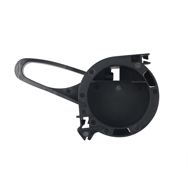
A ladder type cable tray tee is a fitting used to create a branch in a cable tray system, allowing cables to be routed in three directions. Its "T" shape provides a secure and efficient way to split cables from a main tray into two separate paths, ensuring organized and flexible. A cable tray tee and tee cover are components used in cable management systems to support and protect electrical and data cables. Here's a brief explanation of each:. Rigid steel cable tray tee fitting with zero tangent, safety bottom, and full accessory support. ventilation to heat producing cable such as power communication and other with the same or different width of the cable run. All fittings are available in sizes and types corresponding to the straight cable tray sections. These fitting are including: elbow, horizontal cross, vertical inside. NOTE : Equal or un equal tees can be supplied. When ordering state widths W1xW2xW3.. Office: 147/22 Nguyen Sy Sach Street, 15 Ward, Tân Binh Dist, HCMC,VN. Is it possible to connect 2 cabletrays with a "branch piece (left picture)" instead of a "tee (right picture)". The tee has 3 connectors, the branch piece only has 1 connector. I would like to ajust the "Type properties -> Fittings -> Tee" with the branch family, but can't get it accomplished.
[PDF]

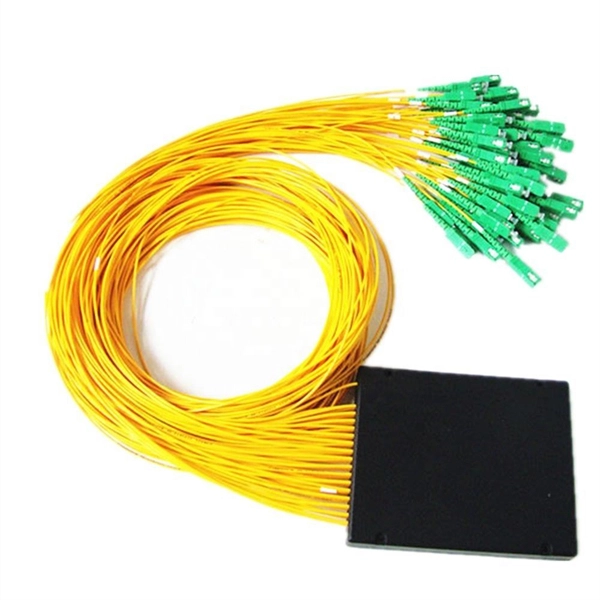
An Optical Splitter, also known as a beam splitter, is a passive optical device that divides a single input optical signal into two or more output signals. Conversely, it can also combine multiple signals into one. Knowing the difference between a splitter and an optical coupler helps you build better networks. You make your network work better when you pick the right device for each job. You can connect many users to one port with 1:n or 2:n splitters. By dividing a single optical signal from a central Optical Line Terminal (OLT) into multiple outputs for Optical Network Terminals (ONTs) at users' homes, splitters eliminate the need for dedicated fibers to each residence—slashing infrastructure costs while scaling network reach. This guide. In a Passive Optical Network (PON), a single optical fiber carries massive amounts of data using light. Signal Input: The fiber splitter receives the optical signal from the upstream network node and enters the splitter through the input fiber. Signal Distribution: Inside the splitter, according to the design structure and different. Splitters are passive optical devices that divide or combine optical signals, and they come in various types, including power splitters, uneven splitters, and wavelength-division multiplexing (WDM) splitters. Each type serves specific applications, enabling efficient use of optical infrastructure.
[PDF]
A fiber optic ring network is a physical or logical network topology where devices (usually switches) are connected in a closed-loop using fiber optic cables. Each node is connected to two other nodes, forming a ring-like structure. This design ensures data can travel in both. This guide walks you through everything you need to know about fiber ring networks—from basic concepts to topology diagrams and essential protocols. Instead of running in a straight line from one point to another, the fiber forms a circular pathway linking multiple nodes. The. An example of this is the SONET/SDH (Synchronous Optical Networking/Synchronous Digital Hierarchy) dual-ring architecture, commonly used in telecommunications. A Metro ring refers to a fiber ring that covers a metropolitan area, connecting multiple locations such as data centers, offices, and. A fiber ring is a specialized configuration of a fiber optic network that arranges the physical transmission lines into a closed loop, or a ring. Data travels around this loop from one device to the next until it reaches its destination. It's one of the fundamental ways to organize a local area network, and while it's less. Network reliability and robustness are critical factors for any organization in the digital age. One approach that has proven effective in achieving these goals is using a fibre ring topology by running multiple redundant geographically different fibre paths to the cabinet. Fibre loops, also known.
[PDF]
CWDM operates on the principle of wavelength multiplexing, where distinct wavelengths carry separate data streams. Each wavelength serves as an independent channel, enabling the transmission of various signals without interference. Here's a breakdown of the process:. In fiber-optic communications, wavelength-division multiplexing (WDM) is a technology which multiplexes a number of optical carrier signals onto a single optical fiber by using different wavelengths (i., colors) of laser light. Learn all about CWDM, how it differs from DWDM, and whether a CWDM solution is right for your business's network. This effectively increases the fiber's capacity, allowing more data to be. The focus of this paper is on the basics of designing and deploying Coarse Wavelength Division Multiplexing (CWDM) systems based on modular Wave-Division-Multiplexing (WDM) technologies and pre-connectorized (“plug-and-play”) solutions. Coarse Wavelength Division Multiplexing (CWDM) is a proven. By comparing CWDM vs DWDM vs MWDM vs LWDM vs SWDM, you can make an informed decision to ensure your network meets your data capacity, distance, and application requirements. As a key offshoot of WDM technology, CWDM (Coarse Wavelength Division Multiplexing) has been widely used in specific scenarios due to its low cost and ease of deployment. Below, ETU will provide a detailed analysis of CWDM, including its definition, operating principles, key characteristics.
[PDF]

This article describes the anti-pumping relay, its definition, function, and circuit diagram. In a circuit breaker it is desired that when close and trip operation is performed on the circuit breaker with the closing coil energized, the subsequent closing operation should be prevented. So let's. Anti-Pumping relay is nothing but a NO contact, which means when the circuit breaker in closed condition the relay will be as NO point and if the circuit breaker in open condition the relay will be as NC Condition. The anti-pumping relays is connected in series with the circuit. An anti pumping relay (also called antipumping relay or Y-relay and ANSI 94 Trip or Trip-Free Relay) is a protective device that prevents a circuit breaker from closing repeatedly when a continuous close command is present. In simple terms, it stops your circuit breaker from “pumping” – which means. Anti-pumping relays are used in circuit breakers to prevent the breaker from closing unexpectedly after tripping. If the TNC switch fails (Trip normal close) or there is any problem with the CB (circuit breakers) closing circuit, the continuous CB (circuit breakers) close command can be extended to. Why is the Anti-Pumping Relay Used? A circuit breaker is a very important equipment for a high-voltage power system. It protects the system from high current or voltage during a faulty condition.
[PDF]
Fiber optic patch panels are enclosures that act as a distribution hub for fiber cable. A bulk (multi-strand) fiber cable enters the patch panel and then each fiber strand is separated into individual strands or pairs of strands. Fiber optic communications has been a rapidly expanding industry for the last 20 years. In its early years, it was mainly used for backhaul communications between large ISP's. But now fiber is widely used and can be found almost anywhere. It's probably in your ofice, on the telephone poles outside. A fiber patch panel is a mounted enclosure—either rack-mounted or wall-mounted—used to terminate, manage, and interconnect multiple fiber optic cables. It acts as a hub for organizing splices and patch cords, streamlining fiber management and preserving signal integrity. It provides a central point where incoming fiber cables can be connected to outgoing patch cords, making the network structured, accessible, and easy to maintain. This makes it easier to alter or troubleshoot the connections as they act as a central point where. Fiber patch panels play an increasingly important role in the optical fiber network due to the widespread use of high-density cabling systems in data centers. They are available in various fiber connector types, such as LC patch panel, SC patch panel and MTP patch panel. This article explores the structure, functionality, types, and benefits of fiber optic patch panels. What's the Fiber Optic Patch.
[PDF]
Thank you very much for purchasing Panasonic products. Read this Instruction Manual carefully and thoroughly for the correct and optimum use of this product. Kindly keep this manual in a convenient place fo.
[PDF]
This relationship is mathematically described by the Beer-Lambert Law, which states that absorbance is directly proportional to the concentration of the substance and the distance the light travels through the solution. The more concentrated a colored solution is, the more light it. A colorimeter is a scientific instrument used to measure the absorbance of light by a colored solution to determine the concentration of solutes. The device operates on the principle that the intensity of the color is directly related to the amount of the colored. Instrumental color measurement moves beyond the limits of human perception and vocabulary and allows us to capture color information as objective data, creating a common language of color that is essential for communication within and between industries around the world, ranging from food and. Colorimeters are built for speed: These devices act as a quick translator for human vision. They are fast, budget-friendly, and perfect for routine pass/fail checks on the factory floor. This is the basis of colorimetry or.
[PDF]
Wide temperature range technology enables devices to operate reliably in extreme temperatures, from freezing to high heat. It is essential for outdoor, military, and industrial environments. Temperature switches are essential devices used to monitor and control temperature in industrial and mobile equipment. They automatically open or close an electrical circuit when a preset temperature is reached, helping protect systems from overheating or unsafe operating conditions. Unlike transmitters that continuously send analog or digital signals, temperature switches provide a discrete ON/OFF output when the measured. What is a temperature switch? A temperature switch or thermal switch is used to open and close switch contacts. The switching status of the temperature switch changes depending on the input temperature. Basically, the thermal. A switch that is used for opening and closing switch contacts is known as a temperature switch. Generally, these switches are. What does a temperature switch do? What is the principle behind mechanical temperature switches? What are electronic temperature switches? What is the switching hysteresis? What is the difference between a temperature switch and a temperature controller? How do bimetal temperature switches work?. These switches play a vital role in ensuring the safety and control of machinery and equipment operating at high temperatures, preventing overheating and potential hazards.
[PDF]

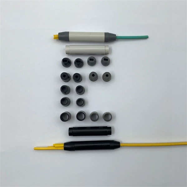
In this case use an optical power meter (OPM) and test the input port of the splitter for the optical power level (dBm) from the OLT at 1490 nm. If there is no or reduced power then the patchcord or OLT is the culprit. If the power level is reduced it could be as simple as a. So for this simple 1X2 splitter, how do we test it? Simply follow the same directions for a double-ended loss test. Attach a launch reference cable to the test source of the proper wavelength (some splitters are wavelength dependent), calibrate the output of the launch cable with the meter to set. Optical splitters in the outside plant (OSP) are used mostly in passive optical networks (PONs) for fiber-to-the-user (FTTx) networks, and are often overlooked as failure points. In this article I focus on a few basics of optical splitters, their applications, typical causes of failures, and how to. Now, we test the simplest 1x2 optical splitter as the picture shown below. 001 dB), OTDR (for reflection event detection). Cleaning tools. The CertiFiber® Pro Optical Loss Test Set (OLTS) can be used to check that the loss of a PON Splitter (often referred to in various standards as a non-wavelength-selective or wavelength-selective branching device) to check that it is within the allowed defined limits. The CertiFiber® Pro has an.
[PDF]

Sensitivity Test: Confirms that the protection works properly for internal defects in the protected zone. Inject primary current via one set of CTs, with one current flowing inward & the other outward. If the CTs are properly connected, there should be no operating current at the. A protective relay is basically an electrical device that detects a fault in a power system and initiates the operation of the circuit breaker to isolate the defective section or component from the rest of the system. In other words, the prime function of protective relays is the timely and. To conduct the tests effectively the following devices and equipment are required: Primary Injection Test Kit – for injecting large currents directly into CT circuits. Secondary Injection Test Kit – Simulates relay inputs with the controlled currents and voltages. It emphasizes selectivity, coordination, fault response, and system behavior rather than individual relay devices. This prevents damage to equipment, reduces downtime, and safeguards. This handbook covers the code of practice in protection circuitry including standard lead and device numbers, mode of connections at terminal strips, colour codes in multicore cables, dos and donts in execution. Its main purpose is to safeguard electrical equipment like transformers, generators, and transmission lines from damage due to.
[PDF]