This article describes the anti-pumping relay, its definition, function, and circuit diagram. In a circuit breaker it is desired that when close and trip operation is performed on the circuit breaker with the closing coil energized, the subsequent closing operation should be prevented. So let's. Anti-Pumping relay is nothing but a NO contact, which means when the circuit breaker in closed condition the relay will be as NO point and if the circuit breaker in open condition the relay will be as NC Condition. The anti-pumping relays is connected in series with the circuit. An anti pumping relay (also called antipumping relay or Y-relay and ANSI 94 Trip or Trip-Free Relay) is a protective device that prevents a circuit breaker from closing repeatedly when a continuous close command is present. In simple terms, it stops your circuit breaker from “pumping” – which means. Anti-pumping relays are used in circuit breakers to prevent the breaker from closing unexpectedly after tripping. If the TNC switch fails (Trip normal close) or there is any problem with the CB (circuit breakers) closing circuit, the continuous CB (circuit breakers) close command can be extended to. Why is the Anti-Pumping Relay Used? A circuit breaker is a very important equipment for a high-voltage power system. It protects the system from high current or voltage during a faulty condition.
[PDF]

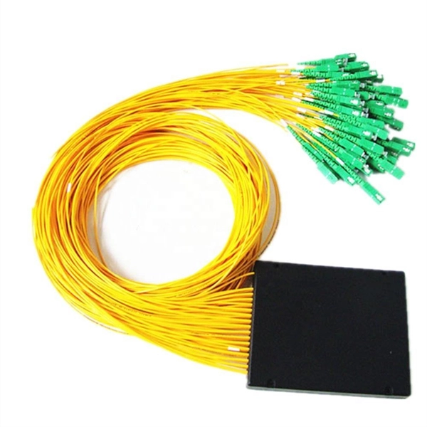
At its core, a fiber termination box combines hardware and software components to facilitate fiber optic connections. The hardware includes protective enclosures, splice trays, adapters, connectors, and patch panels. A Fiber Terminal Box (FTB) is a customer-side termination and distribution device used at the end of the optical network. It is small, so it is considered a mini version of the optical distribution frame or optical distribution frame (ODF). The number of ports of fiber optic junction boxes ranges from 8. A fiber optic junction box, also known as a fiber optic distribution box or termination box, is a protective enclosure that facilitates the connection and management of fiber optic cables. It serves as a central point for organizing and distributing optical fibers, ensuring efficient connectivity. Fiber termination boxes are essential components in modern telecommunications infrastructure. They serve as the critical junction points where fiber optic cables connect, splice, and distribute data signals efficiently and securely. Here's a structured breakdown. This article provides an in-depth comparison of fiber terminal boxes and junction boxes to help clarify their differences and deepen your understanding.
[PDF]

Sensitivity Test: Confirms that the protection works properly for internal defects in the protected zone. Inject primary current via one set of CTs, with one current flowing inward & the other outward. If the CTs are properly connected, there should be no operating current at the. A protective relay is basically an electrical device that detects a fault in a power system and initiates the operation of the circuit breaker to isolate the defective section or component from the rest of the system. In other words, the prime function of protective relays is the timely and. To conduct the tests effectively the following devices and equipment are required: Primary Injection Test Kit – for injecting large currents directly into CT circuits. Secondary Injection Test Kit – Simulates relay inputs with the controlled currents and voltages. It emphasizes selectivity, coordination, fault response, and system behavior rather than individual relay devices. This prevents damage to equipment, reduces downtime, and safeguards. This handbook covers the code of practice in protection circuitry including standard lead and device numbers, mode of connections at terminal strips, colour codes in multicore cables, dos and donts in execution. Its main purpose is to safeguard electrical equipment like transformers, generators, and transmission lines from damage due to.
[PDF]

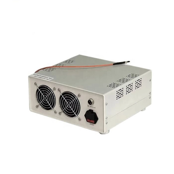
It connects to two independent power sources, enabling automatic switching to a secondary source during primary source failures. This seamless transition prevents disruptions to connected devices and enhances operational reliability. A dual power switching box is precisely the kind of gadget that guarantees a constant flow of electricity as it enables the user to shift the operational state between two different energy supplies. It can be found in homes, workplaces, factories, and anywhere else where sudden cuts of energy can. The ATS Dual Power Distribution Box plays a pivotal role in providing efficient low-voltage power solutions, ensuring that power flows seamlessly, even in the event of an outage. This comprehensive guide offers insights into the mechanisms and benefits of the ATS Dual Power Distribution Box. Transfer switches and sub panel boxes are key components in dual power switching cabinets. Transfer switches automatically switch between power sources during outages, ensuring uninterrupted power and system reliability. This redundancy ensures that if one power source fails, the other can immediately take over, minimizing downtime and preventing. A dual power switch helps you manage two power sources for one system. You can use it to keep your equipment working if the main power stops. This device quickly changes from the main supply to a backup source. This seamless transition.
[PDF]
Thermal relays are the perfect solution for providing protection to motors which provides the most precise tripping for the electric motor during single phasing and overload. This article discusses an overview.
[PDF]
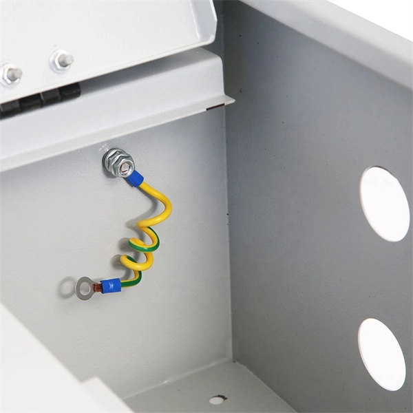
Labérine Énergie offers electrical distribution cabinets: from 30 to 60 Amperes in Blue Tariff and from 160 to 400 Amperes in Yellow Tariff. GlobalTenders collects tender notices, contract awards, procurement opportunities from various sources in Gabon. Protected by a thick sheet metal casing, these distribution cabinets are designed for temporary installations and, thanks to double insulation, meet safety. ENERGYBOX is a complete range of Assemblies for Construction Sites (ACS) pre-wired boards that can be wall-mounted or installed on a support. The panels are made in a sturdy and handy two-component technopolymer cabinet with a fire-resistant backrest, which allows them to be stored and reused in. BOSECKER construction site power distributors are designed and manufactured in accordance with the manufacturer standard IEC 61439 and user standard IEC 60364. The robust sheet steel housing has been. It provides temporary electrical distribution before the electrical panel is installed. It provides standard electrical sockets as well as circuits adapted to the needs. Distribution box cost encompasses various factors that influence the overall investment in electrical distribution systems. A distribution box serves as a crucial component in electrical installations, housing circuit breakers, fuses, and other protective devices that ensure safe power distribution.
[PDF]
7 meters) high makes it easily accessible without the need to bend or stretch excessively. This height also safeguards the box from potential water spills or accidental impacts. The proper installation of a distribution box involves placing it at the right height to ensure safety and convenience. ALL DIMENSIONS ARE CONSIDERED FROM FINISHED FLOOR AND, UNLESS NOTED OTHERWISE, SHALL NOT VARY. ALL DIMENSIONS SHALL BE COORDINATED WITH ARCHITECTURAL DETAILS AND MAY BE. Due to the long time interval between the embedding of the box and the installation and wiring of the box panel, the box shall be disassembled with the box cover (door) and the panel first, and marked for storage, so as to prevent the electrical components and the box cover (door) from damage or. TO EVERY CIRCUMSTANCE OR ELECTRICAL SYSTEM. SRP ENCOURAGES EACH USER TO CONSULT WITH ITS OWN TECHNICAL ADVISOR CONCERNING THE APPLICABILITY OF THESE TANDARDS TO THE USER'S SPECIFIC SITUATION. THE USER ASSUMES ALL RIS USE OF OR RELIANCE ON THESE SPECIFICATIONS. ALL REPRESENTAT ERIA ND FACILITIES. The exposed bottom edge of the lighting box in the basement is 1. 7m away from the ground, the installation height of the control box is 1. 2 Setting and Removing Meters - None but duly authorized agents of the Company or persons authorized by law shall set or remove, turn on or turn off, or make any changes which will affect the accuracy of such meters. Connections to the Company's system are to be made only by its employees.
[PDF]
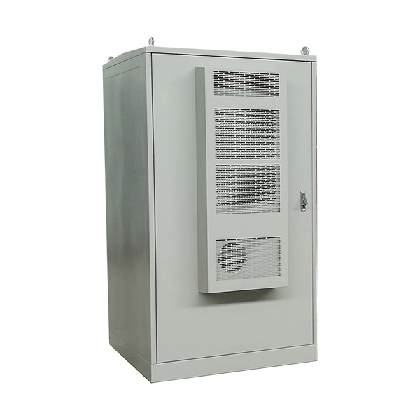
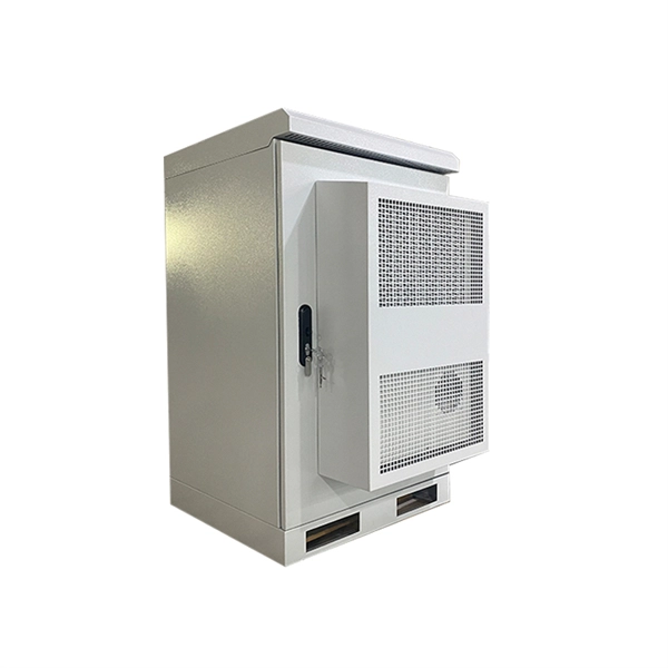
Through a real deployment case using E-abel server cabinets, we illustrate how cabinet design and connector architecture improve power reliability, reduce maintenance complexity, and support the increasing power density of modern data centers. Managing and installing a rack power distribution unit (PDU) has never been easier than with the EL2P PDU. Designed to simplify deployment and take stress out of power distribution, this intelligent PDU helps reclaim valuable hours. Whether that means speeding up Saturday installs or focusing on. An Intelligent Power Distribution Unit (iPDU), also known as a Smart PDU or Intelligent PDU, is a critical component in modern data center infrastructure. The units are available in horizontal 19-in. rack or vertical mounting capabilities. Why Has the Selection of Rack PDUs Become So Important?. For power distribution requirements of medium to large data centers, Delta's Power Distribution Unit (PDU) is an optimal solution. The space-saving PDU is easy to move and adapt to the future demands of the data center. The PDU offers superior power protection and monitoring, and the flexibility. Modern infrastructures typically rely on rack-level Power Distribution Units (PDUs), industrial CEE connectors, and structured cabinet designs to manage power connections efficiently. This article explores how power is connected inside modern data center racks, examining the flow of electricity.
[PDF]
In fiber optic circuit technology an optical fiber link is used for transferring digital or analogue data in the form light frequency through a cable which has a highly reflective central core. Internally, the optical fiber.
[PDF]
This page describes the structure, working operation, advantages, and disadvantages of a Fiber Bragg Grating (FBG) Sensor. Fiber optic sensors work by modulating one or more properties of the light wave, such as intensity, phase, polarization, and frequency. Fiber Bragg grating (FBG) sensors have emerged as advanced tools for monitoring a wide range of physical parameters in various fields, including structural health, aerospace, biochemical, and environmental applications. This review provides a comprehensive overview of FBG sensor technology. A fiber Bragg grating (FBG) is a type of distributed Bragg reflector constructed in a short segment of optical fiber that reflects particular wavelengths of light and transmits all others. An optical fiber typically consists of a. Abstract: Fiber grating sensors are more stable, more reliable and more accurate than traditional electromechanical sensors in many aspects. It can be used to sense and measure physical quantities such as stress, strain or temperature with high sensitivity and measurement range. In this paper, the. Optical fiber sensors (OFS) appeared just after the invention of the practical optical fiber by Corning Glass Works in 1970, now Corning Incorporated, that produced the first fiber with losses below 20 dB/km. At the beginning of this era, optical devices such as laser, photodetectors and the.
[PDF]
This relationship is mathematically described by the Beer-Lambert Law, which states that absorbance is directly proportional to the concentration of the substance and the distance the light travels through the solution. The more concentrated a colored solution is, the more light it. A colorimeter is a scientific instrument used to measure the absorbance of light by a colored solution to determine the concentration of solutes. The device operates on the principle that the intensity of the color is directly related to the amount of the colored. Instrumental color measurement moves beyond the limits of human perception and vocabulary and allows us to capture color information as objective data, creating a common language of color that is essential for communication within and between industries around the world, ranging from food and. Colorimeters are built for speed: These devices act as a quick translator for human vision. They are fast, budget-friendly, and perfect for routine pass/fail checks on the factory floor. This is the basis of colorimetry or.
[PDF]
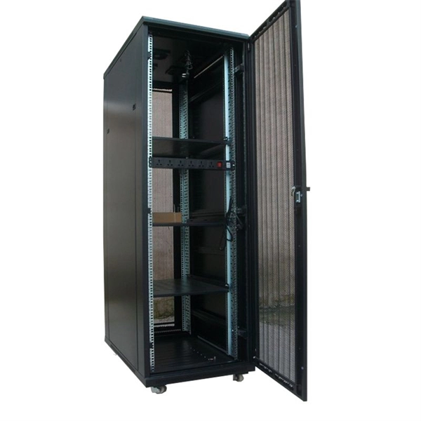
A patch panel is a passive hardware unit that consolidates multiple network connections in one location. Typically rack-mounted, it features ports on the front for easy access and termination points at the back for permanent cabling. From the outside, network planning can look like “run cables, place a switch, get the internet working. By linking wall outlets or devices to network switches through. Ever opened a server room and felt like you walked into a jungle of tangled cables? You're not alone. Businesses of all sizes wrestle with messy wiring, slow troubleshooting, and inconsistent connectivity. But here's the thing: it doesn't have to be that way. The unsung hero behind neat, efficient. We manufacture globally recognized cable management systems and tools designed for your network racks. Explore our product brochure, NIS2 whitepaper, and much more. designed to u2028help you understand our solutions and make informed decisions. Discover who we are and how we're shaping the future. Enter the dynamic duo of **patch panels and racks**: your knights in shining armour against cable clutter. Imagine them as multi-port outlets, neatly organising incoming and outgoing. A fiber patch panel is a mounted enclosure—either rack-mounted or wall-mounted—used to terminate, manage, and interconnect multiple fiber optic cables. It acts as a hub for organizing splices and patch cords, streamlining fiber management and preserving signal integrity. Cable Organization:.
[PDF]
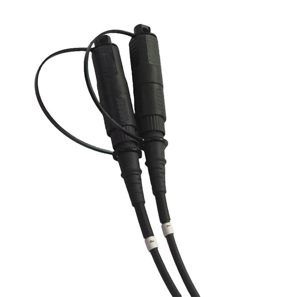
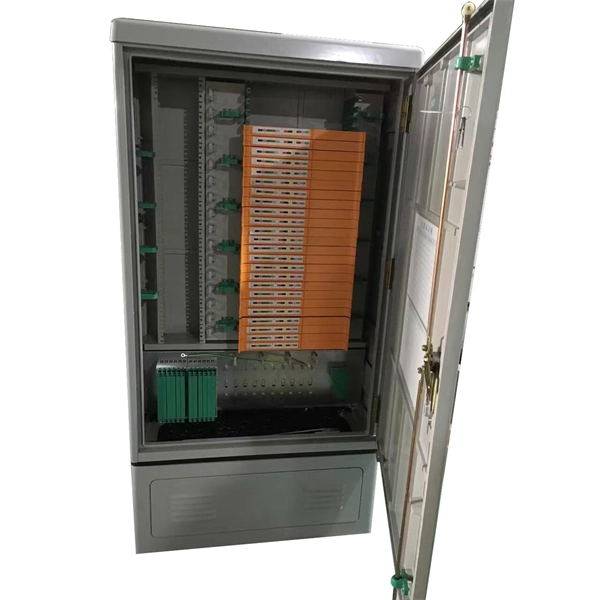
An optical junction box is a vital component in fiber optic networks. It serves as a termination point for fiber optic cables, providing protection and distribution of the optical fibers while ensuring efficient signal transmission. Optical cable junction boxes play a crucial role in connecting and protecting optical fibers, directly influencing the quality and lifespan of optical cable routes. As the demand for high-speed internet and reliable telecommunications increases, the. What is an optical cable splice box Optical cable splice box is a popular name, its scientific name is optical cable splicing box, also known as optical cable splicing package, optical cable splicing package and gun barrel. It belongs to the mechanical pressure sealing joint system and is a splice. --- Optical Fibre Junction Boxes are critical components in the realm of telecommunications, serving as the interfacing point for optical networks.
[PDF]
A fiber optic ring network is a physical or logical network topology where devices (usually switches) are connected in a closed-loop using fiber optic cables. Each node is connected to two other nodes, forming a ring-like structure. This design ensures data can travel in both. This guide walks you through everything you need to know about fiber ring networks—from basic concepts to topology diagrams and essential protocols. Instead of running in a straight line from one point to another, the fiber forms a circular pathway linking multiple nodes. The. An example of this is the SONET/SDH (Synchronous Optical Networking/Synchronous Digital Hierarchy) dual-ring architecture, commonly used in telecommunications. A Metro ring refers to a fiber ring that covers a metropolitan area, connecting multiple locations such as data centers, offices, and. A fiber ring is a specialized configuration of a fiber optic network that arranges the physical transmission lines into a closed loop, or a ring. Data travels around this loop from one device to the next until it reaches its destination. It's one of the fundamental ways to organize a local area network, and while it's less. Network reliability and robustness are critical factors for any organization in the digital age. One approach that has proven effective in achieving these goals is using a fibre ring topology by running multiple redundant geographically different fibre paths to the cabinet. Fibre loops, also known.
[PDF]
This section includes guidelines for the construction, installation, and inspection of electrical systems. Review Part 4, “Highway Traffic Signals,” of the California Manual on Uniform Traffic Control Devices; Calif.
[PDF]