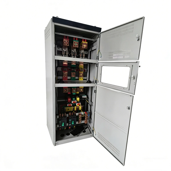
M8 Mild steel fixings should be torqued to 28 NM (20. For reliable busbar connections, component selection matters—but torque control matters more. Best practices include: Yet even with perfect hardware, insufficient torque leads to high resistance. Proper busbar torque specification ensures enough compressive force to stabilize resistance over. Page 1 Medium-Voltage Switchgear Type 8DB10Extendable Fixed-Mounted Circuit-Breaker Switchgear up to 40. 5 kV Double Busbar, Single-pole Metal-Enclosed, Gas-Insulated Medium-Voltage Switchgear INSTALLATION AND OPERATING INSTRUCTIONS Order No. 9 Revision: 06 Issue: 26-02-2016. Failure to follow these instructions can result in injury or equipment damage. The elastic washers placed on the external sides of the connections and busbars help ensure for. At its core, busbar design must meet stringent industry standards, primarily addressing four key areas: thermal performance, mechanical strength, material selection, and electrical integrity. This comprehensive approach ensures that busbars operate stably under rated current conditions and can. Only install switchgear in closed rooms suitable for electrical equipment. Ensure that installation, operation and maintenance are carried out by specialist electricians only. Fully comply with the legally recognized standards (IEC or local), the connection conditions of the local electrical.
[PDF]
Busbars are essential components in electrical power systems, designed to distribute power efficiently within switchgear, panel boards, and distribution boards. Made from copper or aluminum, they serve as a central point where multiple circuits can connect, ensuring stable and. A bus bar (also spelled busbar) is a metallic strip or bar used in electrical power distribution to conduct electricity within a switchboard, distribution board, substation, or other electrical apparatus. Its primary role is to carry large current loads and connect multiple circuits together. In virtually every piece of electrical equipment—from switchgear and power distribution panels to EV battery packs and AI data centers—busbars play a vital, if often unseen, role. These components are the silent conductors of power, ensuring efficient energy distribution, reliability, and compact. Busbars (bus bars) are a type of electrical conductor that, compared to traditional cables, allow for the transmission of current in a safer and more flexible manner. They ensure efficient and effective energy distribution, successfully powering single- and three-phase devices and machines, and. Busbars offer a clean, efficient way to manage power distribution, simplifying complex wiring jobs and boosting reliability.
[PDF]
In , a busbar (also bus bar) is a metallic strip or bar, typically housed inside,, and for local high current power distribution, transmission, or switching substations. They are also used to connect high voltage equipment at electrical switchyards, and low-voltage equipment in. They are generally uninsulated, and have sufficient stiffness to be s.
[PDF]
Multimode Fiber Optic Receivers are devices designed to interpret information contained in optical signals transmitted through multimode fibers. These receivers convert the optical signals into electrical signals, allowing the data to be processed and utilized by electronic systems. Multimode Fiber. They convert electrical signals into optical signals for transmission over fiber-optic cables and reverse the process at the receiving end. Now, the term 'multimode' stems from the fact that these transceivers use multimode fiber (MMF) cables, which can carry multiple beams of light — or 'modes' —. Multi-mode optical fiber is a type of optical fiber mostly used for communication over short distances, such as within a building or on a campus. Multi-mode links can be used for data rates up to 800 Gbit/s. Most systems operate by transmitting in one direction on one fiber and in the reverse direction on another fiber for full duplex operation. For applications where long-haul transmission is unnecessary, multimode SFP modules offer a practical. They have a wider core (around 50 to 62. 5 micrometers), which enables multiple modes or light paths to coexist within the fiber, thus resulting in modal dispersion at shorter distances but reducing its efficacy over longer stretches. The choice between Single-Mode Fiber (SMF) and Multimode Fiber.
[PDF]
Supported by air within insulated pillars, the busbar collects incoming electricity and conducts it for distribution to outgoing feeders. They are typically made from solid or hollow conductive metals, such as copper, aluminum, or brass. In electric power distribution, a busbar (also bus bar) is a metallic strip or bar, typically housed inside switchgear, panel boards, and busway enclosures for local high current power distribution, transmission, or switching substations. Its primary role is to carry large current loads and connect multiple circuits together. Think. A bus bar offers a low electrically resistant path to incoming or outgoing currents. Find out more about them in this article. What is a bus bar? An electrical bus bar is a solid-state conductor made from copper and aluminum- present in the industry for over 150 years. It carries higher amount of currents in a limited space and to which all the incoming and outgoing feeders are connected in a substation.
[PDF]

An Optical Splitter, also known as a beam splitter, is a passive optical device that divides a single input optical signal into two or more output signals. Conversely, it can also combine multiple signals into one. Knowing the difference between a splitter and an optical coupler helps you build better networks. You make your network work better when you pick the right device for each job. You can connect many users to one port with 1:n or 2:n splitters. By dividing a single optical signal from a central Optical Line Terminal (OLT) into multiple outputs for Optical Network Terminals (ONTs) at users' homes, splitters eliminate the need for dedicated fibers to each residence—slashing infrastructure costs while scaling network reach. This guide. In a Passive Optical Network (PON), a single optical fiber carries massive amounts of data using light. Signal Input: The fiber splitter receives the optical signal from the upstream network node and enters the splitter through the input fiber. Signal Distribution: Inside the splitter, according to the design structure and different. Splitters are passive optical devices that divide or combine optical signals, and they come in various types, including power splitters, uneven splitters, and wavelength-division multiplexing (WDM) splitters. Each type serves specific applications, enabling efficient use of optical infrastructure.
[PDF]

A ladder type cable tray tee is a fitting used to create a branch in a cable tray system, allowing cables to be routed in three directions. Its "T" shape provides a secure and efficient way to split cables from a main tray into two separate paths, ensuring organized and flexible. A cable tray tee and tee cover are components used in cable management systems to support and protect electrical and data cables. Here's a brief explanation of each:. Rigid steel cable tray tee fitting with zero tangent, safety bottom, and full accessory support. ventilation to heat producing cable such as power communication and other with the same or different width of the cable run. All fittings are available in sizes and types corresponding to the straight cable tray sections. These fitting are including: elbow, horizontal cross, vertical inside. NOTE : Equal or un equal tees can be supplied. When ordering state widths W1xW2xW3.. Office: 147/22 Nguyen Sy Sach Street, 15 Ward, Tân Binh Dist, HCMC,VN. Is it possible to connect 2 cabletrays with a "branch piece (left picture)" instead of a "tee (right picture)". The tee has 3 connectors, the branch piece only has 1 connector. I would like to ajust the "Type properties -> Fittings -> Tee" with the branch family, but can't get it accomplished.
[PDF]
A PLC Splitter takes one optical signal and splits it into many outputs. This helps share signals in fiber optic networks. Pick the split ratio that matches what you need. Lower ratios work for fewer users. Choose the connector type like SC . PLC optical splitters (planar waveguide optical splitter) is a key component in optical fiber communication networks and is widely used in optical fiber distribution systems such as FTTH (fiber to the home) and PON (passive optical network). A fiber optic PLC splitter distributes a single optical signal into multiple outputs with high uniformity and low loss, making it ideal for. PLC splitter, also called Planar Waveguide Circuit splitter, is a device used to divide one or two light beams into multiple light beams uniformly or combine multiple light beams to one or two light beams. It is a passive optical device with many input and output terminals, especially applicable to. What Is a PLC Fiber Splitter? A PLC (Planar Lightwave Circuit) splitter is a passive optical device that evenly distributes optical signals into multiple output ports using silica waveguide technology. Choose the connector type like SC, LC, or FC. This. That's where PLC splitters come in. These compact passive components help service providers and network engineers distribute a single optical signal across multiple outputs without the need for power or complex configurations. If you're building or upgrading a fiber network and wondering what a PLC.
[PDF]

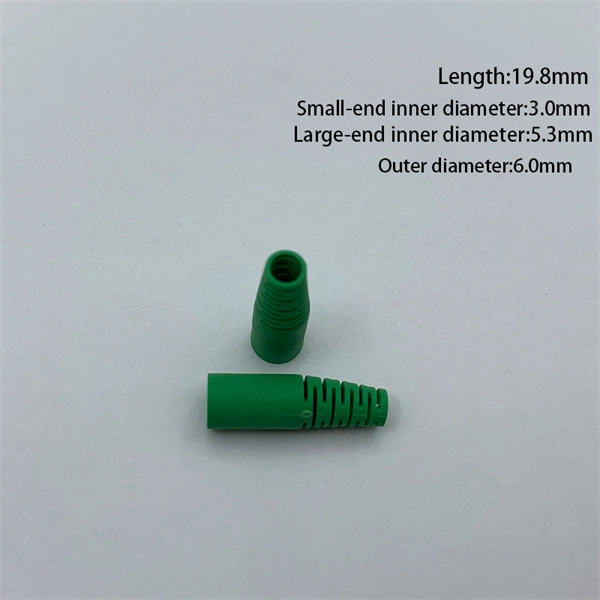
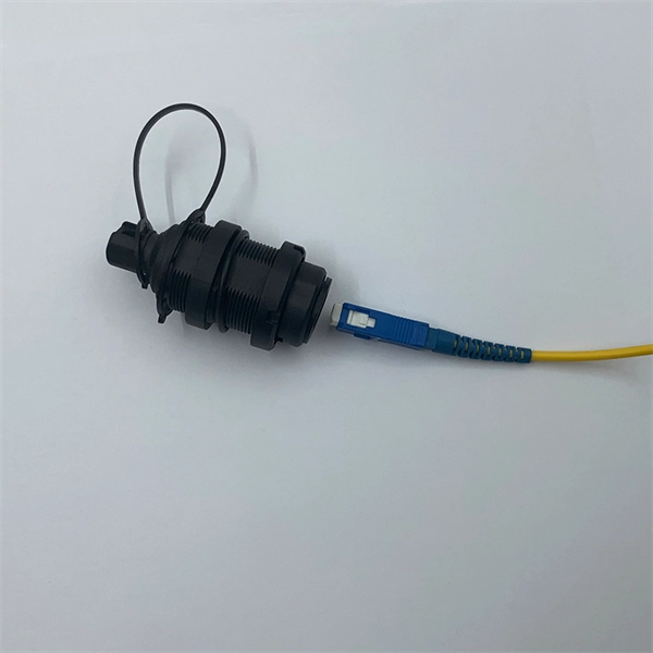
Protect fiber optic cable connections:The joint box provides physical protection for the fiber optic cable connection parts to prevent damage to the fiber optic cable caused by external environmental factors such as moisture, dust, chemical corrosion and mechanical damage. Provide a stable. Fiber optic sleeves are protective devices used for fiber optic connections. Splice protection sleeve, usually made of plastic or metal, are used to secure and protect the fusion joint between two optical fibers. Fiber Cable Joint Box is attributed to the mechanical pressure sealing joint system. Fiber Cable Joint Box is a continuous protection device for supplying optical, sealing and mechanical strength continuity between adjacent optical. The optical fiber terminal box is the terminal joint of an optical cable, one end of which is an optical cable, and the other end is a pigtail, which is equivalent to a device that splits an optical cable into a single optical fiber. The user optical cable terminal box installed on the wall, its. Fiber Optic Splice Closure is designed to protect optical fibers from debris, dirt, dust, moisture and water. As much of the fiber system is outside in a harsh environment, these fiber optic splice closures are designed to meet the tough protection requirements of fiber-optic splices. UnitekFiber. Overview Application of Optical Fiber Splice Closure/Joint Box/Joint Closure: 1. CATV environment.
[PDF]
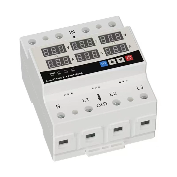
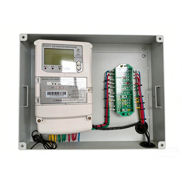
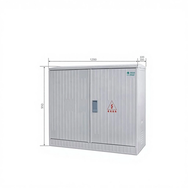
A power distribution unit (PDU) is a device fitted with multiple outputs designed to distribute electric power, especially to racks of computers and networking equipment located within a. Data centers face challenges in power protection and management solutions. This is why many data centers rely on PDU monitoring to improve efficiency, uptime, and growth. For data center applications, the power requi.
[PDF]
Semiconductor laser diodes range widely in price based on a few key parameters. The wavelength, power, spectral qualities, package type, cavity type and quantity will all have an effect on the price. You can buy a laser diode for less than a dollar. Laser Diodes and Modules are semiconductor devices that can emit a beam of high intensity focused radiation, typically in the infrared, visible or ultraviolet wavelength ranges of the electromagnetic spectrum, coherently (light waves of the same wavelength, phase and direction). With power ranges. - 514nm laser diode optimized for life-science applications, housed in a TO-56 Metal Can® package. Laser Diodes are available at Mouser Electronics. Mouser offers inventory, pricing, & datasheets for Laser Diodes. But the price can also be in the tens of. Laser Diodes | UV | 375 - 400 nm Laser Diodes | VIOLET | 405 - 415 nm Laser Diodes | BLUE | 420 - 488 nm Laser Diodes | GREEN | 510 - 520 nm Laser Diodes | RED | 635 - 655 nm. Mideo Systems Inc, FOI-150 Fiber Optic Illuminator Mircoscope Light Source. WeCreat 2W IR Vision 1064nm Infrared Laser PL2302 Incomplete Missing Connection! Get the best deals on Laser Diodes when you shop the largest online selection at eBay. Free shipping on many items | Browse your favorite. This DFB laser diode (1310nm or 1550nm) has InGaAs monitor photodiode and optical isolator integrate. This 1310 nm DFB laser is a specially designed laser module for high performance analog optical tran.
[PDF]
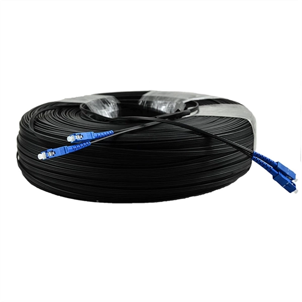
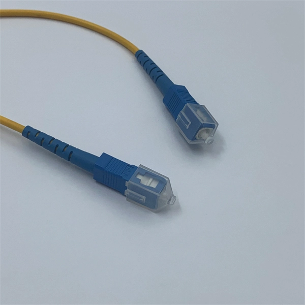
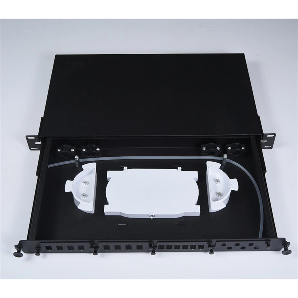
They are the bridge between fiber optic cables in the field and the equipment or patch panels that manage them. By combining factory-installed connectors with spliced bare fiber, pigtails ensure that network installers can create fast, reliable, and cost-effective terminations. Each splice tray includes one or more slots containing fusion, mechanical, or pigtail splices and single mode or modes splicing configurations. Tampering with such splice trays would render the fibers unbent and significantly reduce the network's likelihood of loss or collapse. As a result, they. Fiber pigtails are simple in appearance, yet essential in function. This article will show you what a fiber optic pigtail is. The success of a network in fiber optic cable installation heavily. This is a technology less than a decade old that combines the splice tray, adapter panel, pre-stripped and routed pigtails and splicing consumables required for optical fiber termination in a single compact cassette. In this article, we will examine the factors that have put the exciting new. A fiber optic pigtail is a type of fiber optic cable with only one end that has a factory-terminated connector and the other end exposed as bare fiber. Hence the connector side can be linked to equipment and the other side melted with optical fiber cables. Fiber optic pigtail are utilized to terminate fiber optic.
[PDF]
A beam splitter or beamsplitter is an that splits a beam of into a transmitted and a reflected beam. It is a crucial part of many optical experimental and measurement systems, such as, also finding widespread application in.
[PDF]
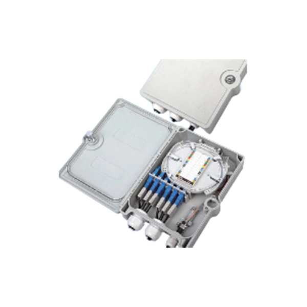
A fiber optic termination box is an enclosure designed to terminate incoming optical fiber cables and distribute optical signals to drop cables or patch cords. It integrates fiber splicing, adapter management, and cable protection in one compact unit. A fiber optic termination box, often called an optical distribution frame (ODF) or fiber patch panel, serves as the endpoint where incoming fibers connect to devices or. A fiber optic termination box is a core component in modern fiber optic networks, providing a secure and organized point for fiber termination, splicing, and distribution. It is widely deployed in FTTH, FTTB, and other access networks to ensure stable signal transmission from backbone cables to end. Fiber termination refers to the process of preparing the end of a fiber optic cable to connect to another fiber, a device, or a network. There are two primary. A Fiber Termination Box, also known as a Fiber Distribution Box, is a crucial component in fiber optic networks. It is a small enclosure that can house and protect the fiber optic cables, splices, and connectors. The fiber termination box. Choosing the right fiber optic terminal box is less about buzzwords and more about matching physics and field reality to your site: where the box will live, how many cores you need now and later, how technicians will access it, and what level of environmental and mechanical protection the network.
[PDF]

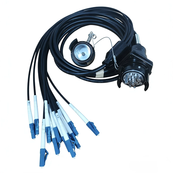
Fiber optic couplers are optical devices that connect three or more fiber ends, dividing one input between two or more outputs, or combining two or more inputs into one output. The device allows the transmission of light waves through multiple paths. These connectors combine the compact form factor of a standard duplex LC with a rugged, waterproof housing, delivering high-performance optical links that withstand rain, dust, temperature. Fiber optic adapters, also known as couplers, play a crucial role in fiber optic networks by providing a connection point between two fiber optic connectors. They enable seamless and reliable optical signal transmission between different fiber optic cables, connectors, or devices. In this tutorial. A fiber coupler is a passive optical device that manages the flow of light signals within an optical network. Directional 2 × 2 couplers (see Figure 1) are usually used for such purposes. This article explores the function, types, and applications of fiber.
[PDF]